
基于单片机步进电机控制系统设计
无需注册登录,支付后按照提示操作即可获取该资料.
基于单片机步进电机控制系统设计(任务书,开题报告,论文20000字)
摘要
步进电动机是一种由电脉冲信号控制的执行元件,由于它具有易控制、体积小等特点,所以在数控系统、自动生产线、自动化仪表、绘图机和打印机等方面有着广泛应用。微电子技术的普及与应用以及微型计算机的飞速发展,逐步进入电机应用领域,这使得之前用硬件电路构成大而复杂的控制器,现在可以用软件来实现。这不仅降低了硬件成本,又提高了控制的灵活性、可靠性及多功能性。由于步进电机具有瞬时启动,急速停止,精度高等特点,用其组成的开环系统既简单、廉价,又非常可行,因此设计出基于单片机的步进电机控制系统具有极大的价值和广泛的应用。
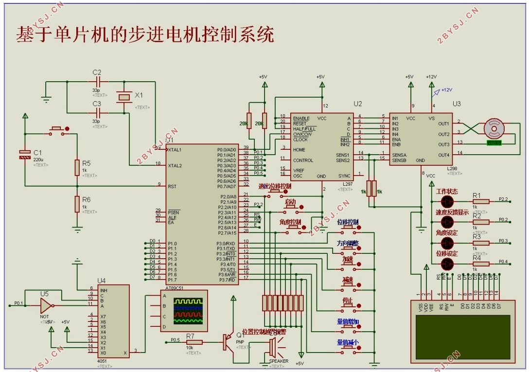
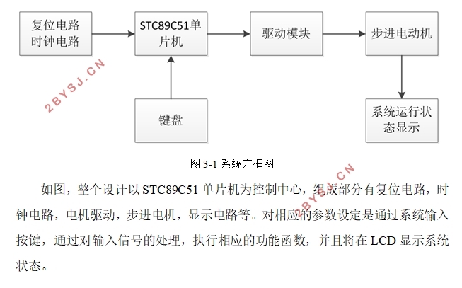
本文课题主要研究了基于单片机的步进电机系统的论证设计。课题内容包括概述步进电机与单片机的工作原理,对步进电机驱动电路进行了分析,以及对系统硬件电路及程序进行了设计与测试。步进电机控制系统的设计采用了软硬件协同仿真的方法,可以有效降低系统开发的时间与成本。利用protues仿真软件完成电机的正反转、加减速、启动停止等基础功能,利用单片机、步进电机驱动芯片、字符型LCD和键盘阵列等元件模块,设计了以控制器与驱动器为一体的步进电机仿真控制系统,实现了对步进电机的方位设定、位置控制等功能,并实时显示出步进电机的工作状态。该系统的硬件组成主要包括控制电路、显示电路、报警反馈电路以及驱动电路组成,根据硬件电路设计出相应的软件程序,进行调试与分析。该设计系统具有思路明确、可靠性高、稳定性强等特点。
关键词:步进电机 驱动电路 单片机 仿真控制系统
Design of stepping motor control system based on single chip microcomputer
Abstract
Stepping motor is a kind of by electric pulse signal to control actuator, because it is easy to control, small size and other characteristics, so in the CNC system, automatic production lines, automatic instrument, drawing machine and printer has a widely application. The popularization and application of microelectronic technology and rapid development of micro computer, and gradually into the application field of the motor, which makes before hardware circuit controller of large and complex can now be used software to achieve. This not only reduces the cost of hardware, but also improves the flexibility, reliability and functionality of the control. Because of the stepper motor with instantaneous start, rapid stop, high accuracy, and with the composition of the open loop system is simple, cheap, and very practical. Therefore, the design of based on single-chip stepper motor control system has great value and broad application.
This paper mainly studies the design of the stepper motor system based on single chip microcomputer. The content of the subject includes the principle of step motor and single chip microcomputer, the stepper motor drive circuit is analyzed, and the system hardware circuit and program are designed and tested. The design of stepping motor control system adopts the method of software and hardware co simulation, which can effectively reduce the time and cost of the system development. Using Protues simulation software to complete the motor positive inversion, deceleration and stop start and other basic functions, using single chip microcomputer, stepping motor drive chip, character type LCD and keyboard array element module, the design of the controller and the driver for one step into the simulation of motor control system, realizes the function of the stepper motor range setting, position control and real-time display of a step into the working state of the motor. The hardware of the system consists of control circuit, display circuit, alarm feedback circuit and drive circuit, the corresponding software program is designed according to the hardware circuit, and the debugging and analysis are carried out. The design system has the characteristics of clear thinking, high reliability, strong stability and so on.
Keywords: stepping motor ;drive circuit;single chip microcomputer;simulation and control system
步进电机的工作原理
步进电机是一种受脉冲驱动的电机。它的工作原理[4]是给电机的绕组按一定的相序分时输入直流电流。当一系列的脉冲信号产生,步进电机就会开始连续的转动。下面就以四相步进电机为例:
首先需要进行脉冲分配,脉冲分配作用就是产生不一样的通电顺序。单四拍的通电顺序为:A-B-C-D-A;双四拍的通电顺序为:AB-BC-CD-DA-AB。正常情况下,步进电机若要正常运行,就必须严格按照此通电顺序。当电机如需要反转时,则可以将通电顺序逆反。在反转状态下,单四拍通电顺序为:A-D-C-B-A;双四拍通电顺序为:BA-AD-DC-CB-BA。

目录
第一章 绪论 1
1.1课题背景 1
1.2课题的目的和意义 1
1.3课题的内容 2
第二章 步进电机的结构与特点 3
2.1步进电机的构造 3
2.2步进电机的工作原理 4
2.3步进电机的主要特征 5
2.4步进电机绕组的电气特性 7
2.5步进电机的选型 8
第三章 设计原理分析 9
3.1设计目的 9
3.2设计要求 9
3.3总体设计方框图 9
3.4设计方案论证 10
3.4.1系统控制方案 10
3.4.2驱动模块方案选择 12
3.4.3最终方案确定 14
第四章 步进电机控制系统硬件设计 15
4.1单片机最小系统 15
4.2 控制电路 17
4.3 驱动电路 19
4.4 显示电路 20
4.5 位移越界报警电路 21
4.6 状态指示灯显示电路 21
第五章 步进电机控制系统软件设计 23
5.1主程序设计 23
5.2 LCD显示程序设计 24
5.3转速控制程序设计 26
5.4程序设计 27
5.5角度设定程序设计 28
5.6位移设定程序设计 29
第六章 仿真结果与分析 33
6.1整体硬件设计图 33
6.2测试 33
6.3误差分析 39
第七章 总结 40
参考文献 41
致 谢 43
附录 44