
200kHz水处理超声功放电路设计
无需注册登录,支付后按照提示操作即可获取该资料.
200kHz水处理超声功放电路设计(23000字)
摘 要
课题来源于国家大学生创新计划项目——超声、臭氧联合污水处理,本文研究的内容是其中子课题之一。
论文主要设计了用于水处理中超声驱动电路的功率放大电路,实现了对100kHz~300kHz方波的功率放大,输出最大功率为100W左右。
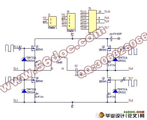
论文深入分析了适用于该大功率驱动电路中开关功率放大器的工作原理。以单相全桥电路为拓扑主回路,根据电路中对频率、功率等参数的要求和通过对不同调制方式的比较。本设计最终采用PDM调制方式,并且选择频率特性高的MOSFET,缩短开断时间,减少了不必要的损耗,提高功率开关管的利用率。
论文根据驱动电路的原理,选择耦合驱动式进行驱动隔离,增强负载驱动能力,提供大电流,并且可以通过自制变压器进行隔离缓冲,实现信号的无失真传输,满足MOSFET开启电压的条件。最终通过系统调试,实现了对压电超声换能器的驱动,验证本文所选方案的正确性和可行性。
论文还分析了LC滤波电路,简单介绍了单级LC滤波器推算原理,并且结合换能器的复杂特性对网络匹配问题进行展望。
关键词:开关功率放大器;PDM;H桥电路;变压器
Abstract
The study described in this paper rooted in a project ultrasonic、ozone sewage treatment. The project was supported by Innovated plan of National University Students. This paper is one of its neutron topics.
The paper has mainly designed power amplified circuit being used for the water treatment drive ultrasonic transducer, it has realized the power amplification being frequency from 100kHz to 300kHz square, the maximum power output is nearly 100W.
In the first place, paper has deeply analyzed the principle for the switching power amplifier which was suitable for the high efficiency driving circuit. The paper has taken single-phase bridge inverter circuit as the topology main circuit. Through the different modulation system's comparison and the parameter of the frequency and power, the paper used the PDM modulation. And according to the circuit value, the paper has chosen MOSFET of the high frequency in order to reduce the on-off time, to increase the utilization, to reduce the nonessential loss.
According to the principle of driving circuit, the paper has used coupling actuation type for carrying on the actuation isolation. It has good capable of driving force and also provides enough electric current. Then through the self-made transformer, it can realize the isolation and the transmission of the non-distorted signal. All of these, it will be benefit for the demand of MOSFET switch voltage. At last, the whole system has been debugged and was able to drive transducer. The design scheme is proven to be the valid and feasible.
The paper also has analyzed the LC wave filter and simply introduced the principle of single stage LC filter. Then from the complex characteristic of ultrasonic transducer the relationship of electrics resistor and ultrasonic frequency combining with changer matching, we will have more to do in the future.
Keywords:Switching power amplifier; PDM; H-bridge; Transformer
1毕业设计目标:
(1)培养综合运用知识,独立开展工程实践的能力;
(2)学会新器件的使用;
(3)掌握功率放大电路的原理及其电路调试;
(4)掌握模拟电路的相关知识,protel电路板设计及PCB制作技术 。
2研究方法及手段应用:
(1) 查阅相关论文资料,并与以往知识相结合,融会贯通;
(2) 向有经验的同学请教;
(3) 自己多动手,多实践。
3毕业设计预期效果:
(1)实现推动变压器的四路无失真波形传输;
(2)实现功率放大电路对换能器的驱动
4平台硬件设计及软件实现:
设计系统平台的基本架构,应用protel设计硬件电路及PCB制版
5熟悉查找资料的方法,掌握研究总结和论文的基本写作要领,学会用多媒体课件言简意赅的报告研究进展。
目录
第一章 绪论 1
1.1 课题简介 1
1.1.1 课题背景 1
1.1.2 课题来源及研究意义 1
1.2 超声水处理对功放的要求 2
1.3 论文的结构及研究内容 2
第二章 功率放大器的工作原理 4
2.1 D类放大器的介绍 4
2.1.1 常见的功率放大器 4
2.1.2 D类放大器 4
2.1.3 D类放大器工作原理 5
2.2 开关功率放大器的调制原理 6
2.2.1 PWM调制分析 6
2.2.2 PDM调制分析 7
2.2.3 功放电路的工作方式 8
2.3 功放电路的效率 8
2.4 本章小结 10
第三章 功率放大器逆变主回路设计 12
3.1 主回路结构 12
3.1.1 推挽式电路 12
3.1.2 半桥式电路 12
3.1.3 全桥式电路 12
3.2 功率开关管的选择 14
3.2.1 整体概述 14
3.2.2 MOSFET的选择 15
3.2.3 芯片IRF840B 18
3.3 本章小结 20
第四章 H桥驱动电路的设计 21
4.1 H桥前级驱动电路 21
4.1.1 驱动方案的选择 21
4.1.2 驱动芯片的选择 22
4.1.3 芯片TPS2811 23
4.2 H桥推动变压器的设计 25
4.2.1 设计的要点 25
4.2.2 变压器的绕制 26
4.3 本章小节 28
第五章 LC滤波电路的设计分析 29
5.1 滤波器的分类 29
5.2 LC滤波电路的设计分析 29
5.2.1 设计LC滤波电路的一般要求 29
5.2.2 单级LC滤波器的分析 30
5.2.3 H桥滤波电路的分析 31
第六章 全文总结与展望 33
致谢 35
参考文献 36
附录一 系统硬件电路图 38
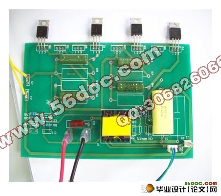
附录二 实物图 39
附录三 翻译 40