
24GHz雷达发射机系统设计(附电路原理图,PCB图)
无需注册登录,支付后按照提示操作即可获取该资料.
24GHz雷达发射机系统设计(附电路原理图,PCB图)(论文12000字,电路原理图,PCB图)
摘要:新世纪以来,随着雷达应用的普及,各式各样的雷达系统应用在各种设备机器上,在这之中,24GHz雷达系统因为其低廉的成本价格、较小的体积要求等优势在雷达市场上获得了广泛的应用,而24GHz雷达发射机作为整个24GHz雷达的关键组成部分之一,又是雷达系统中最金贵的部件,在雷达市场上受到了极大的关注,有着光明的未来前景。本人在之前一些学者的研究基础上,研究了24GHZ雷达发射机系统的搭建,结合ADS仿真和PCB板图设计,确定了发射机的各个性能指标,通过ADS射频仿真软件获得了设计的雷达发射机重要的各项性能指标数据,并将这些性能指标参数加以分析,判断其是否满足雷达发射机的性能要求,并根据这些参数选择符合设计要求的混频器,功放芯片,通过AD软件进行PCB板图绘制,画出核心器件的PCB板图,设计出满足实际生产要求的雷达发射机系统。
关键词:24Ghz;雷达发射机;雷达系统;ADS仿真;PCB板图
Simulation and Design of 24GHz Radar transmitter system
Abstract: In the new century, with the popularity of radar applications, a variety of radar systems are applied to various equipment and machines. Among them, the 24GHz radar system, because of its low cost and price, Small volume requirement has been widely used in radar market. As an important part of radar system, 24GHz radar transmitter is also the most expensive part of radar system, and it has received great attention in the radar market. There are bright prospects for the future. On the basis of some previous scholars' research, I have studied the construction of 24GHZ radar transmitter system, combined with ADS simulation and PCB board diagram.The performance parameters of the designed radar transmitter system are obtained by ADS radio frequency simulation software, and the performance parameters of the radar transmitter system are analyzed. Judging whether it meets the performance requirements of radar transmitter, selecting mixer and amplifier chip according to these parameters, drawing the PCB board diagram by AD software, drawing the PCB board diagram of the core device, and using these parameters to select the mixer and amplifier chip which meet the design requirements, and draw the PCB board diagram of the core device. A radar transmitter system is designed to meet the requirements of practical production.
Key words: 24GHz; Radar transmitter; Radar system; ADS Simulation; PCB Board Diagram
目 录
一、引言 1
(一)研究意义 1
(二)研究现状 1
(三)本文工作内容 2
二、设计方案概述 3
(一)设计目的 3
(二)模块设计 3
1. IF信号源模块设计 4
2. 带通滤波器模块设计 4
3. 功率放大器模块设计 5
4. 混频器模块设计 5
5. 衰减器模块设计 6
三、ADS仿真结果及分析 6
(一)ADS仿真结果 6
(二)重要性能指标分析 8
1. 系统输出功率 8
2. 链路增益分析 9
3. 噪声系数分析 10
4. 输出三阶交截点分析 11
5. 1dB增益压缩点分析 12
(三)设计要求和仿真分析 13
四、PCB板图设计 13
(一)芯片选择方案 13
1. HMC311ST89芯片 13
2. HMC260LC3B芯片 14
3. HMC499LC4芯片 16
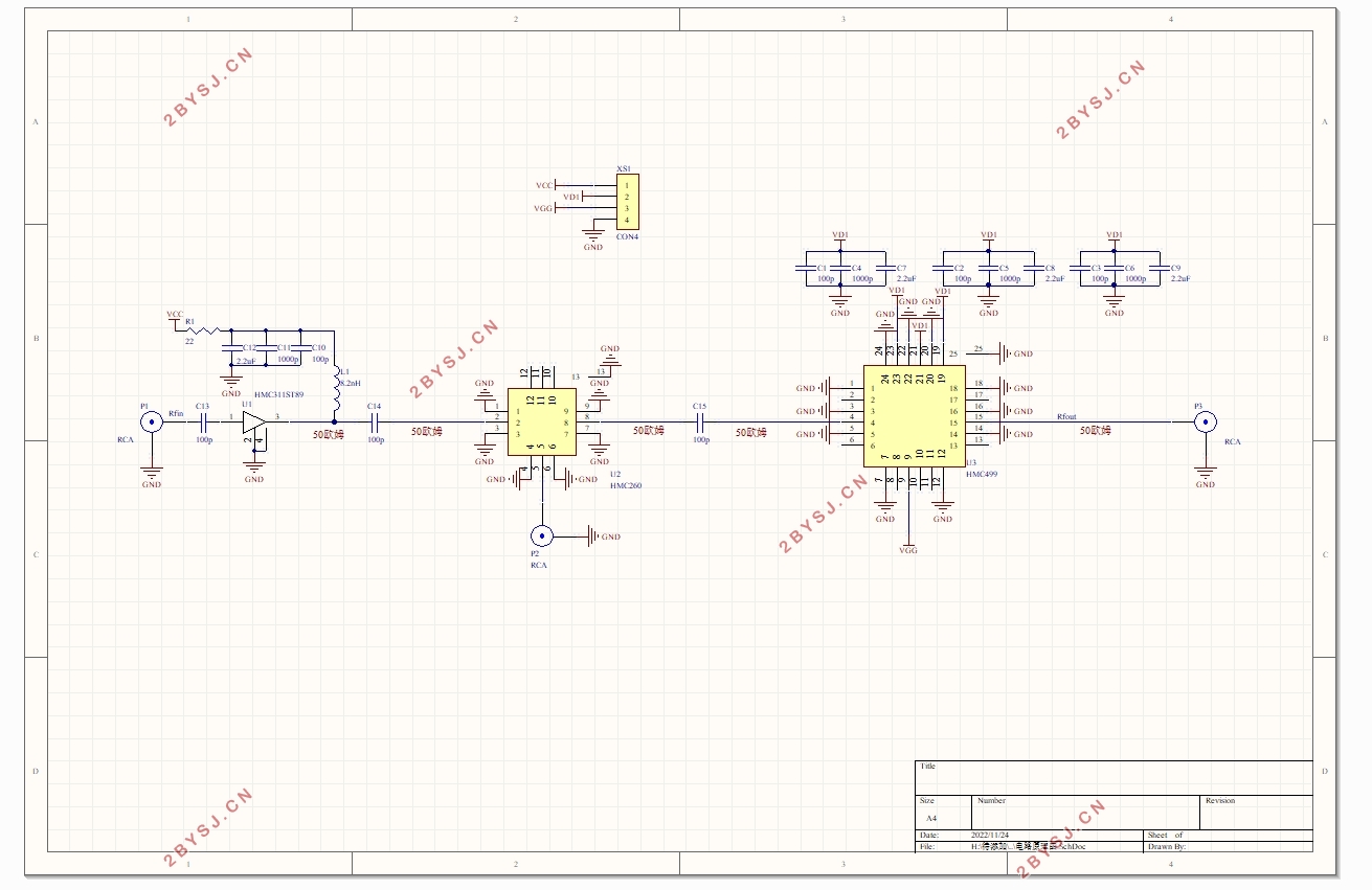
(二)PCB原理图 17
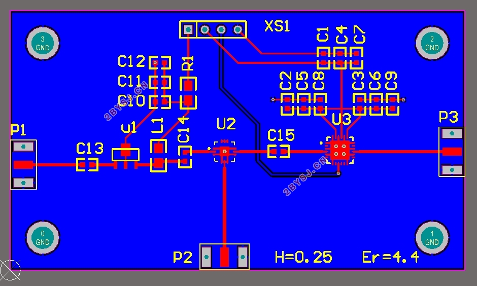
(三)PCB核心器件板图 18
1. 板材参数选择 18
2. 微带线宽度计算 18
3. PCB板图成果 18
五、结论 19
参考文献 19
致谢 21