
超声振动磨削机构的建模与仿真(CAD,SolidWorks三维)
无需注册登录,支付后按照提示操作即可获取该资料.
超声振动磨削机构的建模与仿真(CAD,SolidWorks三维)(任务书,开题报告,外文翻译,论文说明书20000字,CAD图纸7张,SolidWorks10张,答辩PPT)
摘要:
超声波加工是一门重要的特种加工技术,超声加工的总概述:其分为超声车、铣、磨、钻等。超声振动磨削是一种特殊的切削加工的方法,这种加工技术对于加工陶瓷、高强度复合材料以及硬脆材料具有独到的优势。本文从超声振动声学子系统设计超声振动磨削机构。从声学角度和波动方程角度分别介绍了变幅杆设计的理论基础。设计了机构与工件相连接以及机构与机床相连接装置。这个超声振动磨削机构,可以直接装配到一般普通机床上直接使用,因此非常方便。这种新型机构可以作为一种机床附件,它具有体积小、结构简单、成本低、可加工大型工件的优点,对超声波加工以及机床的发展具有十分重要的意义。
关键词:超声波发生器,换能器,变幅杆,珩磨头。
ABSTRACT:
The ultrasonic machining is an important special machining technology, is the supersonic processing total outline: It divides into the supersonic vehicle, the mill, to rub, to drill and so on. The ultrasonic vibration grinding is one special machining method, this kind of process technology regarding the ceramics, the high strength compound materials as well as the hard crisp material has the original superiority. This article from ultrasonic vibration acoustics system design organization. Introduced the amplitude pole design rationale from acoustics angle and the wave equation angle. Has designed the organization and the work piece connects as well as the organization and the engine bed junction device. Designs this ultrasonic vibration grinding organization, may assemble directly to the engine bed on the direct use. This kind of new organization may take one kind of engine bed appendix, has the volume to be small, the structure is simple, the cost low merit, has the vital significance to the ultrasonic machining as well as engine bed’s development.
Key words: Ultrasonic generator, transducer, amplitude pole, top horizontal jade piece wheel head.
课题研究的内容
课题研究的内容有以下六点:
1. 超声加工机床进行分析,通过和普通机床的比较,研究一种新的机构,使其可以安装在普通机床上便可进行超声加工。
2. 变幅杆是超声波机床振动系统的重要组成部分,本文将从声学角度和波动方程角度来探讨变幅杆的设计和珩磨头的设计问题。
3. 对变幅杆进行结构分析和动力学分析。
4. 为满足不同用户的要求,以超声电源功率250W的磨削头结构为基型产品,对其进行系列化设计。
5. 对超声振动磨削机构进行三维建模。
6. 对本课题的内容做出结论和展望。
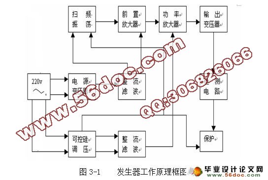
本设计所采用的超声发生器与换能器参数如下:
超声发生器频率f=20kHz;
换能器输出端尺寸66mm,输入电压220V,连续工作时间30-60min。

目 录
第一章 绪 论 5
1.1 引言 5
1.2 超声振动磨削机构概述 5
1.3 超声波的产生及其特性 6
1.4 超声波加工发展概况 7
1.5 课题研究的内容 7
第二章 超声振动磨削系统的总体机构设计 9
2.1 引言 9
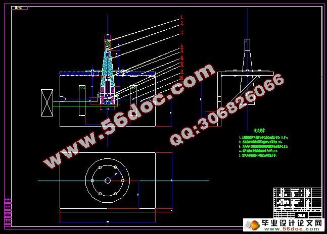
2.2 超声振动磨削系统的结构设计 9
2.2.1 超声波机床与普通机床的异同点: 9
2.2.2 超声振动磨削系统基本结构的确定 10
第三章 超声振动磨削机构声学子系统的设计 12
3.1 超声波发生器与换能器 12
3.2 超声变幅杆的设计 14
3.2.1 变幅杆的功用 14
3.2.2 变幅杆的振动形式及特点 15
3.2.3 变幅杆的类型分析和比较 16
3.2.4 变幅杆类型的选择 18
3.2.5 变幅杆材料的选择 19
3.2.6 变幅杆的设计与解析 20
3.2.7 变幅杆各参数的计算 25
3.2.8 变幅杆与换能器的连接 27
3.2.9 变幅杆的固定 27
3.3 轴瓦的设计与连接 28
3.4 外固定套的设计与连接 29
3.5 油石的选择 30
3.6 螺钉 、双头螺柱、 垫圈和梯形螺栓的选择 32
3.6.1 螺钉的选择 32
3.6.2 双头螺柱的选择 32
3.6.3 垫圈的选择 33
3.6.4 梯形螺栓的选择 33
第四章 超声振动磨削机构建模 34
4.1 三维建模软件 34
4.2 对超声振动磨削机构进行建模 39
4.2.1 变幅杆的三维建模与三维建模步骤 39
4.2.2 刀杆的三维建模与三维建模步骤 40
4.2.3 轴瓦的三维建模与三维建模步骤 41
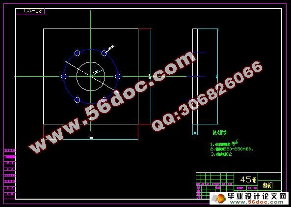
4.2.4 支架的三维建模与三维建模步骤 42
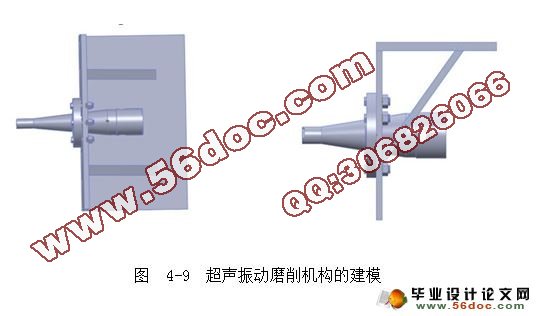
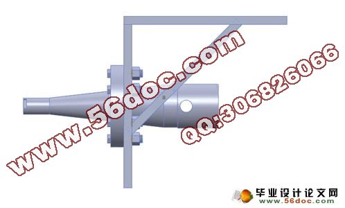
4.2.5 超声振动磨削机构的三维建模与三维建模步骤 43
第五章 结论和展望 44
5.1 结论 44
5.2 展望 44
参 考 文 献 45
致 谢 46
附录一 英文科技文献翻译 47
附录二 毕业设计任务书 66