
直角式可控调速装置机械系统的设计(含CAD零件图装配图)
无需注册登录,支付后按照提示操作即可获取该资料.
直角式可控调速装置机械系统的设计(含CAD零件图装配图)(开题报告,中期检查表,外文翻译,论文说明书12300字,CAD图10张)
摘 要
在煤炭工业发展过程中,长距离、大运量、大功率的带式输送机的应用越来越广泛。而合理的带式输送机的驱动方式已成为长距离、大运量、大功率的带式输送机的一个瓶颈,因而我们要求带式输送装置具有较好的力矩。直角式可控调速装置就可满足该要求,可实现速度控制功能。
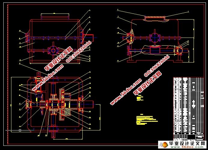
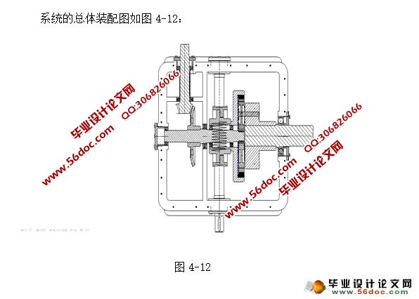
直角式可控调速装置是在原有普通的2K--H型行星齿轮减速器的基础上展开的,并进行了改良与创新,使得原有的单一减速功能变为由液压马达实现的可控调速的高性能的减速装置。该装置的设计采用了机械传动、液压传动与现代电器控制技术想结合,构思新颖独特,且方案在技术上是切实可行的,有一定的创新性。直角式可控调速装置总体结构简单,制造容易,并与采煤生产密切相结合,具有广泛的推广与应用前景。
关键词:直角 调速 行星齿轮 减速器
Abstract
In the process of coal industry development in long distance,large capacity, high power belt conceyor application more and more widespread. Reasonable belt converor drivng mode has become a long distance, large capacitity, high power belt conveyor of a bottleneck. Therefore we request a belt conveying device has good torque. Right angle type controlled speed regulating device can meet the requirement, which can realize the speed control function.
The right-angle type device that can control of changing the speed is a function in the original common 2K--H plant wheel gear , which to go forward the improvement and innovation, make the only-one lower the speed function change into be press by the liquid the motor carry out of can control to adjust the speed of the deceleration of high performance equip. This equipment's design project adoption machine spreeds to move, the liquid presses to move control the technique with modern electric appliances to combine together, conceive outline novel, the project is on the technique is to slice actually viable, have the innovation and unique, the total structure is simple, make easily, the cost is low with adopting the coal production to combine together closely, having the extensive expansion application foreground.
Key words: Right-angle; Changing the speed; Plant gear; The machine of lowering the speed
目 录
前 言 1
1 系统的方案设计 3
1.1 问题的提出及发展前景 3
1.2 系统的工作原理 4
1.2.1 行星轮 5
1.2.1.1 行星轮的特点 5
1.2.1.2 行星轮传动的类型 6
1.2.1.3 行星轮的制造与安装 6
1.2.2 圆锥齿轮 7
1.2.3 蜗轮蜗杆 8
1.2.3.1 蜗轮蜗杆的双重作用 8
1.2.3.2 蜗轮蜗杆的安装与制造 9
2 系统的传动设计 10
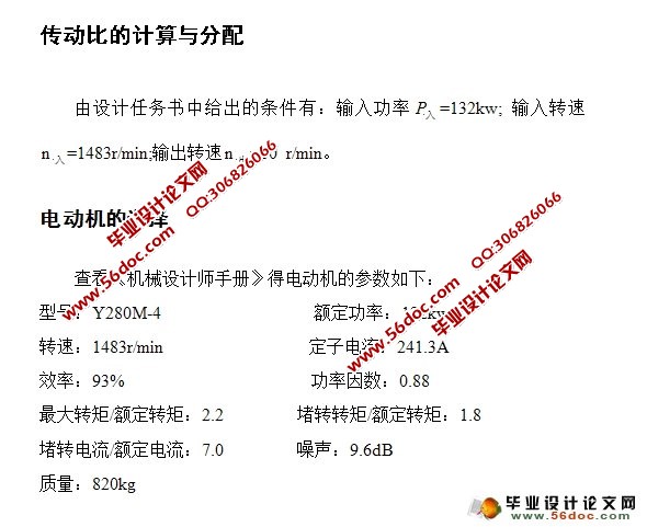
2.1 传动比的计算与分配 10
2.1.1 电动机的选择 10
2.1.2 传动比的计算 10
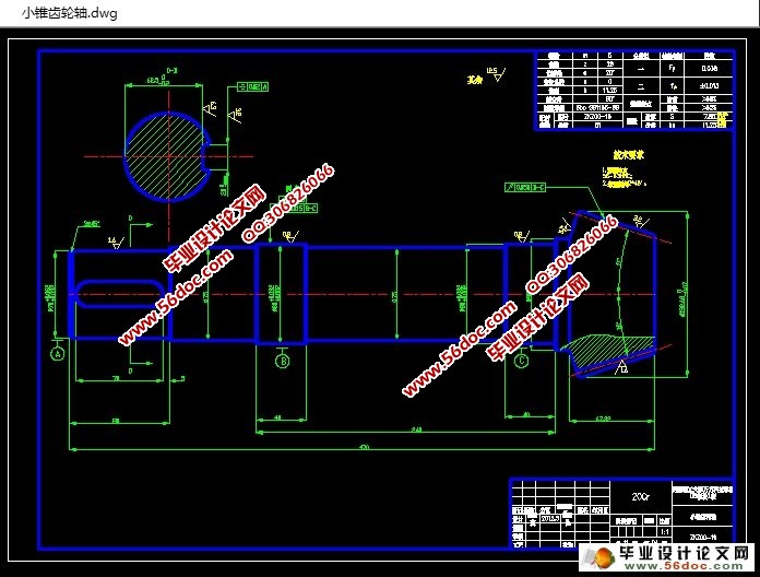
2.2 锥齿轮的传动设计 11
2.2.1 确定齿轮的类型、精度等级、材料和齿数 11
2.2.2 按齿面接触强度设计 11
2.2.2.2 计算 13
2.2.3 校核齿根弯曲疲劳强度 14
2.2.3.1确定弯曲强度载荷系数 14
2.2.3.2 计算当量齿数 15
2.2.3.3 确定相关修正系数 15
2.2.3.4 计算弯曲疲劳许用应力 15
2.3 行星齿轮的传动设计 20
2.3.1 材料的选择 20
2.3.1.1 太阳轮和行星轮 20
2.3.1.2 内齿圈 20
2.3.2 确定各主要参数 20
2.3.2.1 传动比 20
2.3.2.2 行星轮数目 21
2.3.2.3 配齿计算 21
2.3.3 几何尺寸计算 24
2.3.4 齿轮强度计算 26
2.3.4.1 齿轮承载能力计算参数 26
2.3.4.2 a-c啮合副的强度校核 27
2.3.4.3 b-c啮合副的强度校核 33
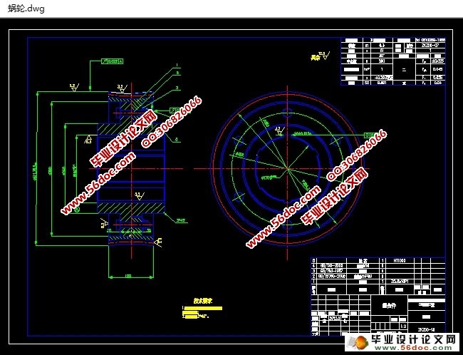
2.4 蜗杆蜗轮的传动设计 37
2.4.1 选择蜗杆的传动类型 37
2.4.2 选择材料 37
2.4.3 按齿面接触疲劳强度进行设计 37
2.4.4 蜗杆与蜗轮的主要参数与几何尺寸 39
2.4.5 校核齿根弯曲疲劳强度 40
3 系统的轴系设计 42
3.1 传动轴的校核 42
3.1.1 选择轴的材料,确定许用应力 42
3.1.2 计算轴的载荷 42
3.1.3 计算轴径 43
3.1.4 轴的受力分析 43
3.2 中间轴的轴承校核 46
3.2.1 轴承的选择 46
3.2.2 轴上的受力分析 46
3.2.3 计算寿命 48
4 传动件的结构设计 49
4.1 小锥齿轮轴的结构设计 49
4.2 大锥齿轮的结构设计 49
4.3 中间轴的结构设计 50
4.4 太阳轮的结构设计 51
4.5 行星轮的结构设计 51
4.6 内齿圈的结构设计 52
4.7 蜗轮的结构设计 53
4.8 蜗杆轴的结构设计 53
4.9 行星架的结构设计 54
4.10 输出轴的结构设计 55
4.11 箱体的结构设计 55
4.12 总装配图 57
结束语 58
致 谢 60
参考文献 61