
飞机轴承端盖冲压模具设计(含CAD零件图装配图)
无需注册登录,支付后按照提示操作即可获取该资料.
飞机轴承端盖冲压模具设计(含CAD零件图装配图)(任务书,开题报告,外文翻译,论文说明书10000字,CAD图5张)
摘 要
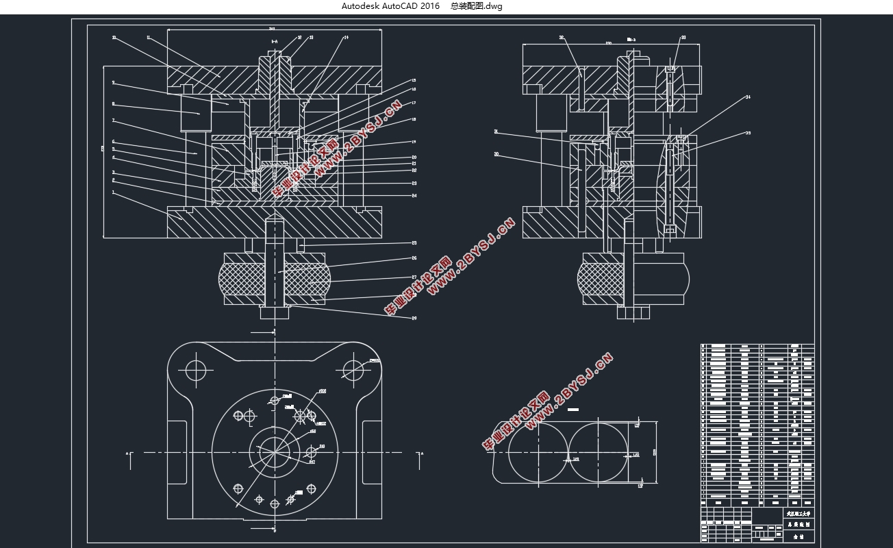
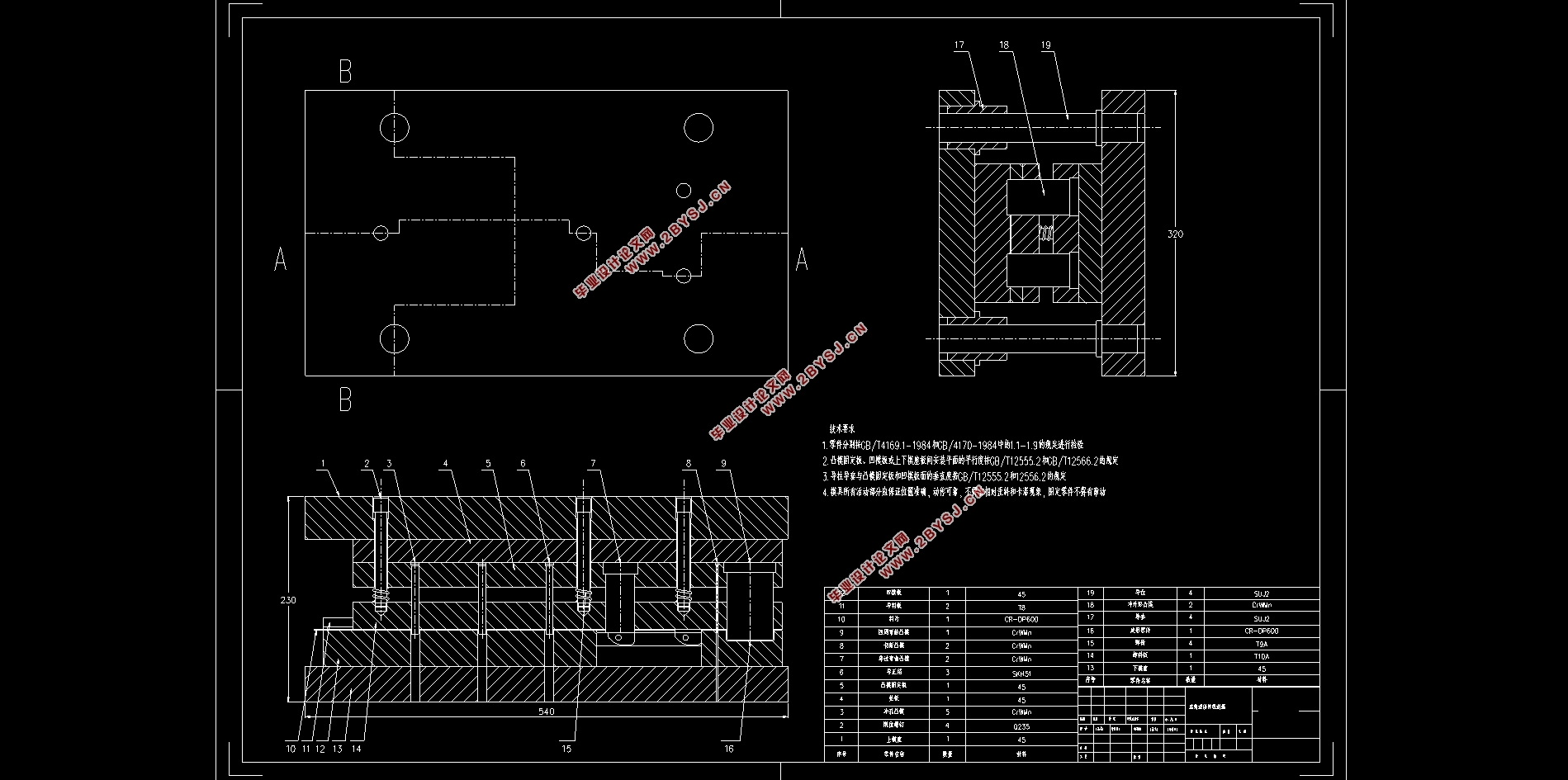
二十一世纪以来,我国社会经济快速发展,科学技术显著进步,模具成型技术也在这个大环境下不断发展前进,目前已经成为现代工业生产的重要手段,由于普遍的应用,这对模具从业者的模具的设计水平也提出了极高的要求。模具生产在航天航空方面的应用也极为突出,飞机零件设计制造的信息化也得到快速发展,利用建模软件来产品的结构设计,模拟生产制造过程,进行工艺分析,技术的发展极大地提高了零件的生产效率和产品质量。冲压技术已经发展成一项极为重要的生产手段。本文针对飞机轴承端盖设计了一套复合模具,来完成端盖的冲压设计,其中包含坯料形状的计算,排样方法的比较、冲压工序的确定、模具零件结构尺寸的确定,标准件的选用、刃口间隙的确定、零件图、装配图的绘制,装配原则的确定等一整套设计流程。通过现代化三维建模软件ProE、二维制图软件AutoCAD,来完成其中的绘图部分,极大地缩短了模具的设计周期,能够提高生产效率,这对于以后的设计工作有很大的借鉴作用。
关键词:冲压模具;工艺计算;设计要求;三维建模
Abstract
Since the 21st century, China’s social and economic development has been rapid, science and technology have made remarkable progress, and mold forming technology has also been continuously advancing in this general environment. At present, it has become an important means of modern industrial production. Due to widespread application, this mold practitioner has The level of design of the mold has also raised extremely high demands. The application of mold manufacturing in aerospace is also extremely prominent. The informationization of aircraft part design and manufacturing has also been rapidly developed. The use of modeling software to design the product structure, simulate the manufacturing process, perform process analysis, and greatly improve the development of technology. Parts production efficiency and product quality. Stamping technology has developed into an extremely important means of production. This paper designs a set of composite molds for aircraft bearing end caps to complete the stamping design of the end caps, including the calculation of the blank shape, the comparison of the layout methods, the determination of the stamping process, the determination of the size of the mold parts, and the selection of standard parts. , Determination of edge clearance, drawing of parts, drawing of assembly drawings, determination of assembly principles, etc. Through the modern three-dimensional modeling software ProE, two-dimensional graphics software AutoCAD, to complete the drawing part, greatly shortened the design cycle of the mold, can improve the production efficiency, which has a great reference for future design work.
Key Words:Stamping die;process calculation;design requirements ;3D modeling
零件的工艺性分析
2.1 分析零件的工艺性
冲压过程包括以下几个主要步骤,坯料的准备—冲压加工工序的确定—必需辅助工序的确定—质量检验,但过程分析的重点关注冲压过程的本身[4]。冲压加工工序很多,各种工序中的工艺性又不都相同。在这里我着重于讨论零件的结构工艺性。
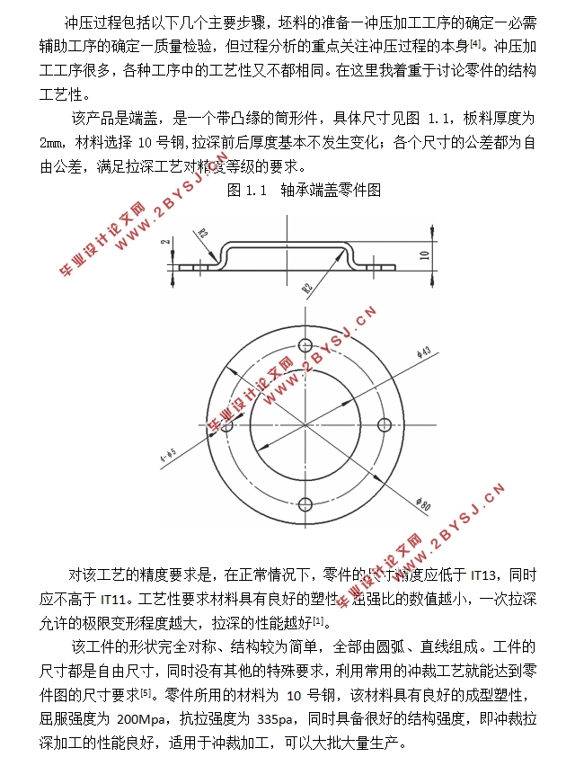
该产品是端盖,是一个带凸缘的筒形件,具体尺寸见图1.1,板料厚度为2mm,材料选择10号钢,拉深前后厚度基本不发生变化;各个尺寸的公差都为自由公差,满足拉深工艺对精度等级的要求。
对该工艺的精度要求是,在正常情况下,零件的尺寸精度应低于IT13,同时应不高于IT11。工艺性要求材料具有良好的塑性,屈强比的数值越小,一次拉深允许的极限变形程度越大,拉深的性能越好[1]。
该工件的形状完全对称、结构较为简单,全部由圆弧、直线组成。工件的尺寸都是自由尺寸,同时没有其他的特殊要求,利用常用的冲裁工艺就能达到零件图的尺寸要求[5]。零件所用的材料为10号钢,该材料具有良好的成型塑性,屈服强度为200Mpa,抗拉强度为335pa,同时具备很好的结构强度,即冲裁拉深加工的性能良好,适用于冲裁加工,可以大批大量生产。
目录
第1章 绪论 1
1.1 设计目的 1
1.2 模具设计主要内容 1
1.2.1 零件工艺性分析 2
1.2.2 确定冲压工序 2
1.2.3工艺参数计算 2
1.2.4 绘制装配图和零件图 2
第2章 零件的公艺性分析 3
2.1 分析零件的工艺性 3
第3章 确定工艺方案 4
3.1 毛坯尺寸的计算 4
3.2 计算拉伸次数 4
3.3 确定是否需要压边圈 4
3.4 确定工艺方案 4
第4章 主要工艺参数的计算 6
4.1 确定排样、裁板方案 6
4.2 计算工艺力、初选设备 7
4.2.1 工艺力计算 7
4.2.2 初选压力计 9
4.2.3 计算压力中心 10
4.2.4 计算凸 凹模刃口尺寸及公差 10
4.2.5 拉深凸 凹模圆角半径的计算 11
第5章 模具的结构设计 12
5.1 模具结构型式的选择 12
5.1.1 模架的选用 12
5.1.2 模具的闭合高度 12
5.1.3 导向零件的选用 12
5.1.4 模柄的选用 13
5.1.5 卸料装置 13
5.1.6 定位装置 13
5.2 模具主要零部件(结构)设计 13
5.2.1 落料凹模 13
5.2.2 凸凹模 14
5.2.3 上垫板 14
5.2.4 压边圈 14
5.2.5 拉深凸模 14
5.2.6 模柄 17
第6章 模具的整体安装 18
6.1 模具装配 18
6.2模具零件 20
第7章 模具的实际装配 22
7.1 复合模具的装配 22
7.2 模具典型零件的装配要点 22
第8章 总结 23
参考文献 24
致谢 25