
矿用自卸车举升机构设计及总体设计(含CAD图,SolidWorks三维图)
无需注册登录,支付后按照提示操作即可获取该资料.
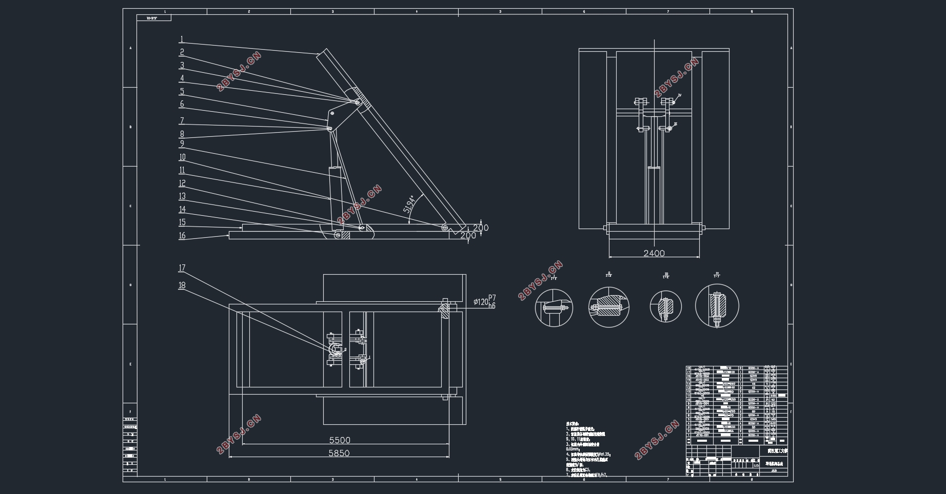
矿用自卸车举升机构设计及总体设计(含CAD图,SolidWorks三维图)(任务书,开题报告,文献摘要,外文翻译,论文说明书11000字,CAD图纸6张,SolidWorks三维图)
摘 要
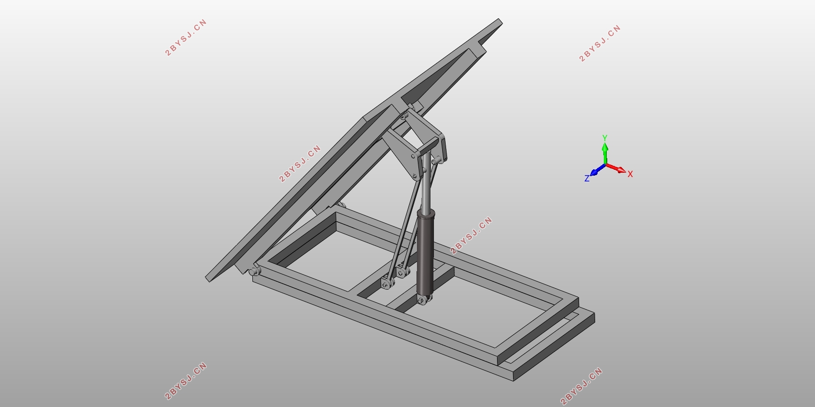
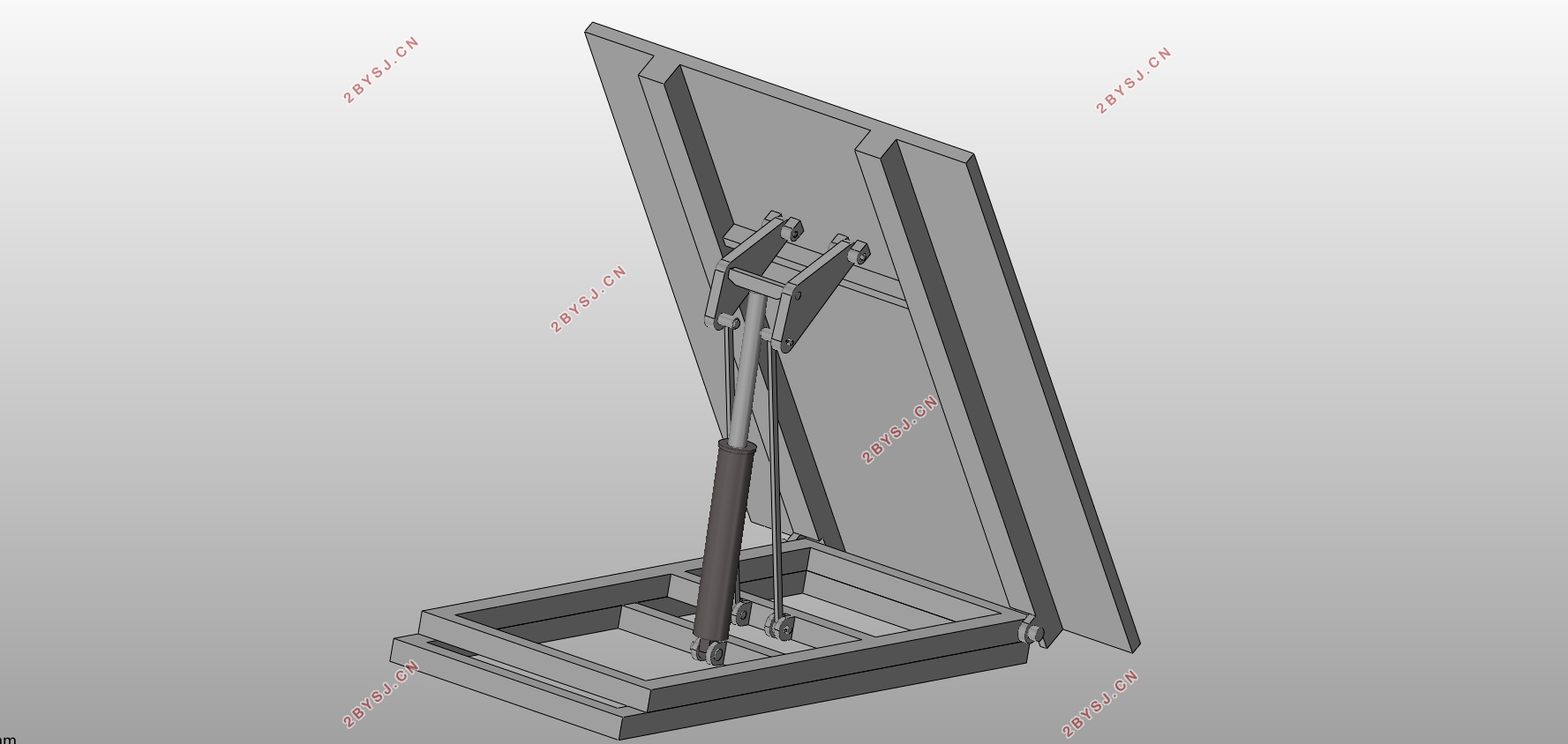
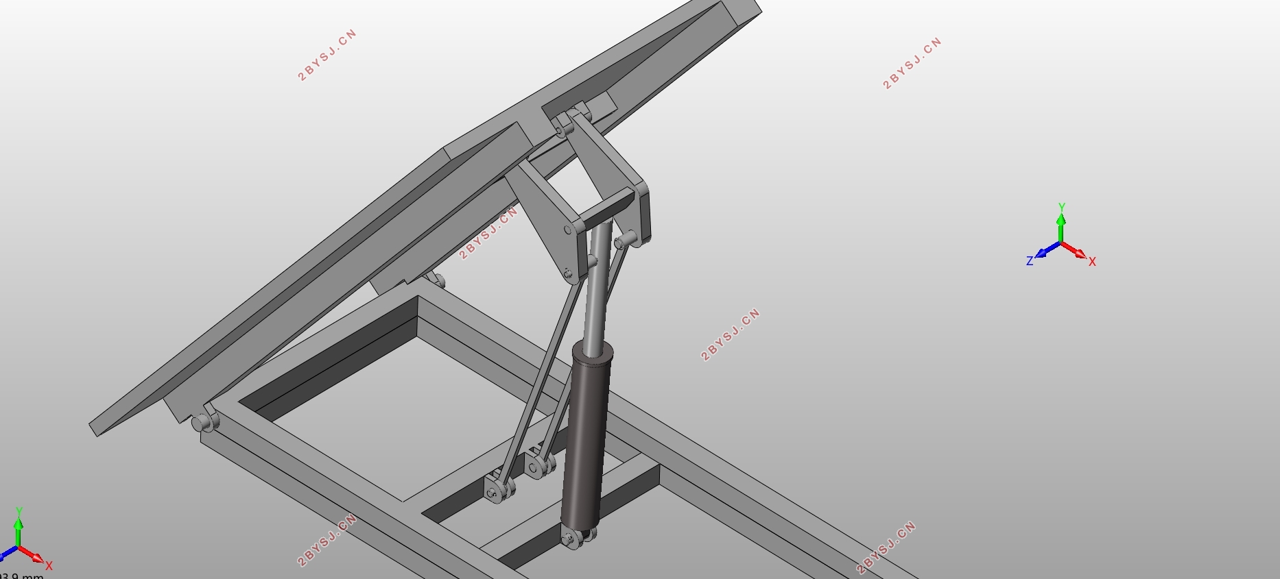
本文通过对各种自卸车举升机构的对比,分析各种举升机构的特性,对选用的举升机构类型进行选择。举升机构类型确定后,通过使用几何作图法来对油缸与车架、拉杆与车架,三角臂与车厢的铰接点进行确定,进而得到活塞杆行程与三角臂及拉杆的尺寸。在结构、尺寸、布置确定之后根据载重量来利用解析法得到力学特性。再通过对极限工况的分析来校核零部件尺寸的合理性以及对液压油缸的选型确定。最后利用三维建模软件对各零部件进行三维建模与虚拟装配,并利用多刚体动力学仿真软件来观察举升机构的运动情况。
本文所用的三维建模软件是达索公司的SolidWorks,完成对自卸车前置前推连杆组合式举升机构各零部件的设计与建模后,对举升油缸总成与举升机构总成进行虚拟装配,随后使用其多刚体系统动力学模块SolidWorks motion来对举升机构进行运动仿真分析,得到相关运动曲线。最后使用有限元分析软件ANSYS Workbench对三角臂的极限工况进行力学分析,验证了设计的合理性。
关键词:自卸车;SolidWorks;T式举升机构;Workbench
Abstract
By comparing the lifting mechanisms of various dump trucks, the characteristics of various lifting mechanisms are analyzed, and the types of lifting mechanisms selected are selected. After the type of lifting mechanism is determined, the hinge points of the oil cylinder, the frame, the pull rod and the frame, the triangular arm and the cargo box are determined by using the geometric drawing method, and then the stroke of the piston rod and the size of the triangle arm and the pull rod are obtained. After determining the structure, size and layout, the mechanical properties are obtained by using the analytical method according to the load capacity. By analyzing the limit conditions, the rationality of parts size and the selection of hydraulic cylinders are checked. Finally, using the three dimensional modeling software to build three-dimensional modeling and virtual assembly, and using the multi rigid body dynamics simulation software to observe the motion of the lifting mechanism.
The three-dimensional modeling software used in this paper is Dassault company's SolidWorks. After completing the design and modeling of the components of the combined lifting mechanism of the front push connecting rod of the dump truck, the assembly of the assembly of the assembly of the cylinder assembly and the lifting mechanism is carried out, and then the lifting mechanism is virtual by using its multi-body system kinematics module SolidWorks motion. Motion analysis and related motion curves were obtained. Finally, using the finite element analysis software ANSYS Workbench to carry out the mechanical analysis of the limit condition of the triangle arm, and verifies the rationality of the design.
Key Words:Dump truck; SolidWorks;T type lifting mechanism;Workbench
目 录
摘 要 I
Abstract II
第1章 绪论 1
1.1 选题背景与意义 1
1.2 国内外发展现状 1
1.3 本文研究的主要内容 2
第2章 多体系统动力学和有限元法简介 3
2.1 多体动力学 3
2.1.1 多体系统动力学简介 3
2.1.2 软件简介 3
2.2 有限元分析 3
2.2.1 有限元分析简介 3
2.2.2软件简介 3
第3章 举升机构的选型及相关参数的确定 4
3.1 举升机构的分类及特性比较 4
3.2 举升机构选型 5
3.3 最大举升角和举升时间与降落时间的确定 6
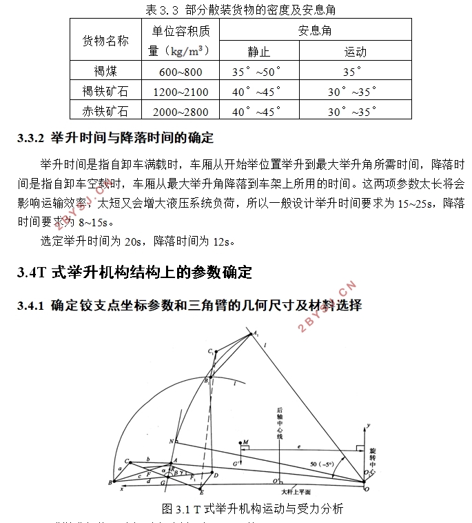
3.3.1 最大举升角的确定 6
3.3.2 举升时间与降落时间的确定 7
3.4T式举升机构结构上的参数确定 7
3.4.1 确定铰支点坐标参数和三角臂的几何尺寸及材料选择 7
3.4.2 T式举升机构运动与受力分析计算 9
3.4.3 拉杆的选材与校核 12
3.4.4 主、副车架的材料的确定 12
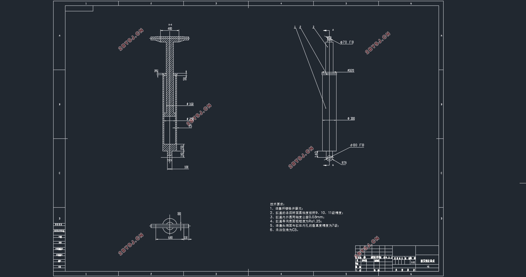
3.5举升油缸的选型与计算 13
3.5.1 举升油缸内径与活塞杆外径的确定 13
3.5.2 举升油缸缸体长度的确定 14
3.5.3 举升油缸壳体壁厚度与材料的确定 14
3.5.4 活塞杆材料与油缸端盖材料的确定 14
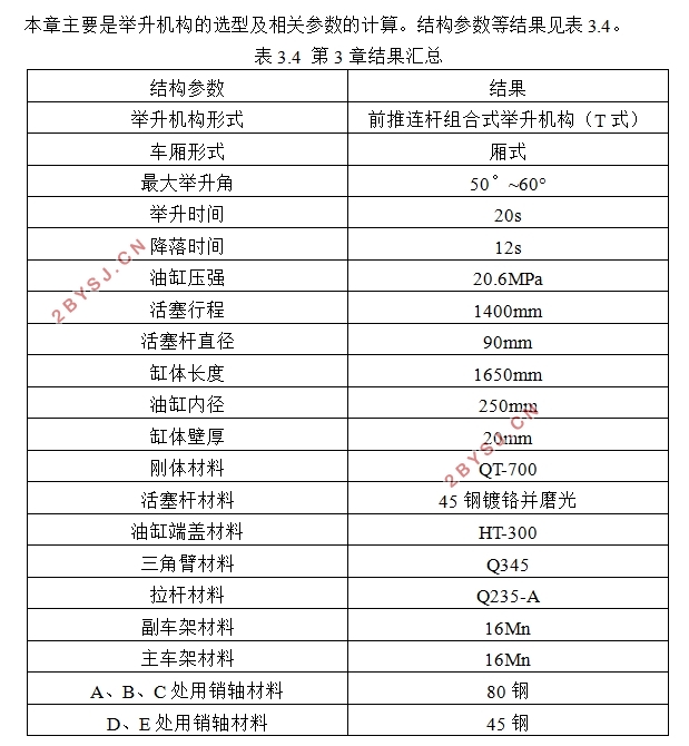
3.6 本章小结 15
第4章 举升机构的三维建模与运动分析 16
4.1 举升机构三维实体模型的建立 16
4.1.1 副车架的三维实体建模 16
4.1.2 主车架的三维实体建模 16
4.1.3 三角臂的三维实体建模 17
4.1.4 拉杆的三维实体建模 17
4.1.5 举升油缸缸体的三维实体建模 17
4.1.6 活塞杆的三维实体建模 18
4.1.7 油缸端盖的三维实体建模 19
4.2 举升机构的虚拟装配与干涉检查 19
4.2.1 油缸总成的虚拟装配 19
4.2.2 举升机构总成的虚拟装配 20
4.2.3举升机构总成的干涉检查 20
4.3运动学仿真 21
4.4 本章小结 23
第5章 有限元分析 25
5.1 模型导入 25
5.2 添加材料 25
5.3 选择材料与网格划分 26
5.4 添加载荷与约束 27
5.5 仿真结果 27
5.6本章小结 27
第6章 结论与展望 28
6.1 结论 28
6.2不足与展望 28
参考文献 29
致谢 30