
WH1090货车驱动桥设计(含CAD零件图装配图)
无需注册登录,支付后按照提示操作即可获取该资料.
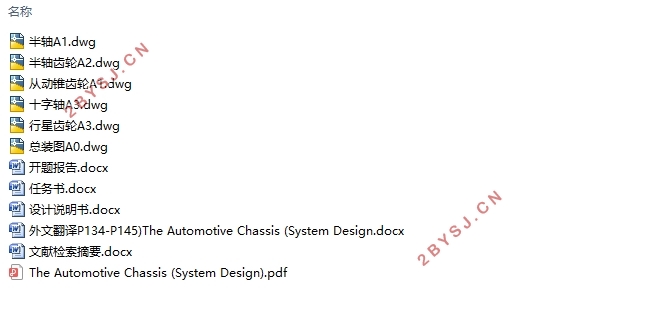
WH1090货车驱动桥设计(含CAD零件图装配图)(任务书,开题报告,外文翻译,计算说明书14600字,CAD图6张)
摘 要
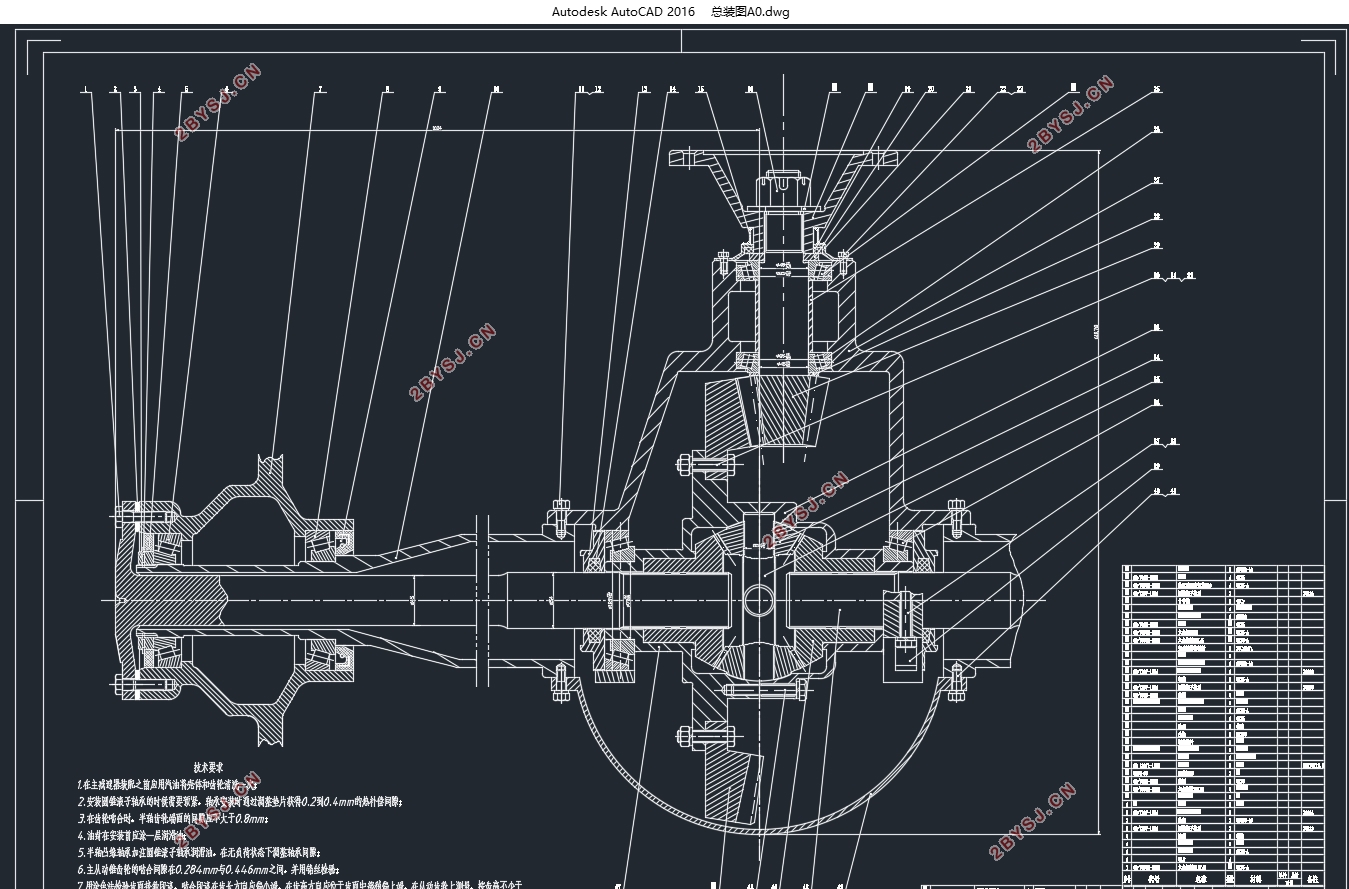
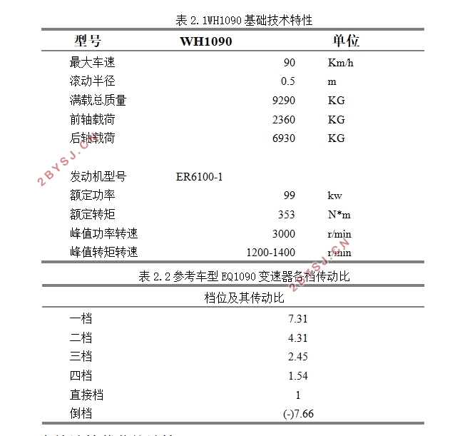
本论文以WH1090货车驱动桥为研究对象,根据给定的车型基础参数,依次对主减速器、差速器、半轴、驱动桥壳进行设计计算。首先是对主减速器的齿轮进行选型、计算并校核,得出选择单级主减速器以及双曲面齿轮副传动的形式。然后,对于差速器进行选型,通过比较各差速器形式优缺点以及考虑汽车使用条件,选择普通对称式圆锥行星齿轮。最后,本文对于半轴和桥壳选用全浮式半轴和整体式桥壳。在设计时,尺寸确定过程中辅以CATIA三维建模,以保证各零件尺寸在装配时不出现干涉,再将各零件由三维图导入AUTOCAD二维图纸中,完成设计任务。
关键词:驱动桥;主减速器;AUTOCAD;CATIA
Abstract
In this paper, Dongfeng WH1090 (WH1090) truck driving axle is used as the research object. According to the basic parameters of the vehicle, the main reducer, differential, axle and drive axle are designed and calculated. First of all, the main reducer gear selection, calculation and verification, obtained the choice of single-stage main reducer and spiral bevel gear sub-transmission form. Then, for the differential selection, by comparing the advantages and disadvantages of the differential form and consider the use of vehicle conditions, select the ordinary symmetrical cone planetary gears. Finally, this paper selects the full-floating axle and the integral axle housing for the axle and axle housing. In the design, the dimension determination process with CATIA three-dimensional modeling to ensure that the parts size in the assembly without interference, and then the parts from the three-dimensional map into the AutoCAD two-dimensional drawings, complete the design task.
Key Words:drive axle;the main reducer;AutoCAD;CATIA
目录
第1章绪论 1
1.1 设计概述 1
1.2 驱动桥设计的现状及分析 1
1.3 驱动桥的设计要求 1
1.4 研究内容及预期目标 2
第2章主减速器设计 3
2.1 主减速器结构方案确定 3
2.1.1 减速形式选择 4
2.1.2 主减速器齿轮类型的选择 4
2.1.3 主动齿轮支承方式和安装方式的确定 5
2.1.4 从动齿轮的支承方式的确定 6
2.2 主减速比的确定 7
2.3 齿轮计算载荷的计算 8
2.4 齿轮参数确定 10
2.4.1 主从动齿轮齿数的确定 10
2.4.2 从动齿轮大端分度圆直径的确定 11
2.4.3 齿轮端面模数的选择 11
2.4.4 齿面宽的确定 11
2.4.5 双曲面齿轮偏移方向及螺旋方向的确定 11
2.4.6 法向压力角的确定 12
2.4.7 主动齿轮偏移距的确定 12
2.4.8 分锥角的确定 12
2.5 主减速器齿轮几何尺寸计算 12
2.6 齿轮强度校核 14
2.6.1 单位齿长圆周力的校核 14
2.6.2 轮齿弯曲强度的校核 15
2.6.3 轮齿接触强度校核 17
2.7 主减速器齿轮材料的选取 18
2.8 主减速器轴承选型与强度校核 18
2.8.1 轴承载荷计算 18
2.8.2 轴承的选型及校核 21
2.9 主减速器的润滑 22
第3章差速器设计 23
3.1 差速器的选型 23
3.2 差速器齿轮基本参数确定 24
3.2.1 行星齿轮数n 24
3.2.2 行星齿轮球面半径Rb 24
3.2.3 行星齿轮、半轴齿轮齿数 24
3.2.4 节锥角及模数m 25
3.2.5 压力角 及齿高系数 25
3.2.6 行星齿轮安装孔直径d及其支撑深度L 25
3.3 差速器齿轮几何计算 26
3.4 差速器齿轮强度计算与校核 27
3.5 差速器齿轮材料的选取 28
第4章传动装置设计 28
4.1 传动装置的确定 28
4.2 半轴设计与计算 29
4.2.1 全浮式半轴尺寸计算及材料选取 29
4.2.2 全浮式半轴载荷计算及校核 30
第5章驱动桥壳设计 31
5.1 驱动桥壳型式的选择 32
5.2 驱动桥壳的强度计算 33
5.2.1 车轮承受切向力最大情况 33
5.2.2 车轮承受侧向力最大情况 34
5.2.3 汽车通过不平路面情况 35
第6章结论 35
参考文献 36
附录A 37
附录B 41
致谢 42