
自动驾驶微型纯电动车制动系设计(含CAD零件图装配图,CATIA三维图)
无需注册登录,支付后按照提示操作即可获取该资料.
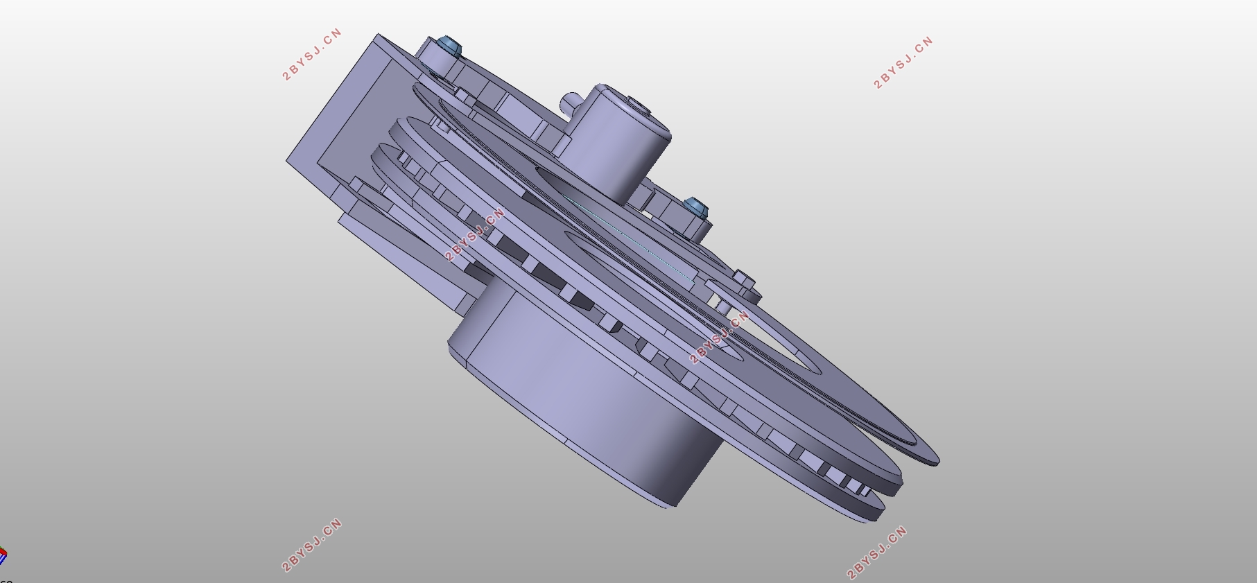
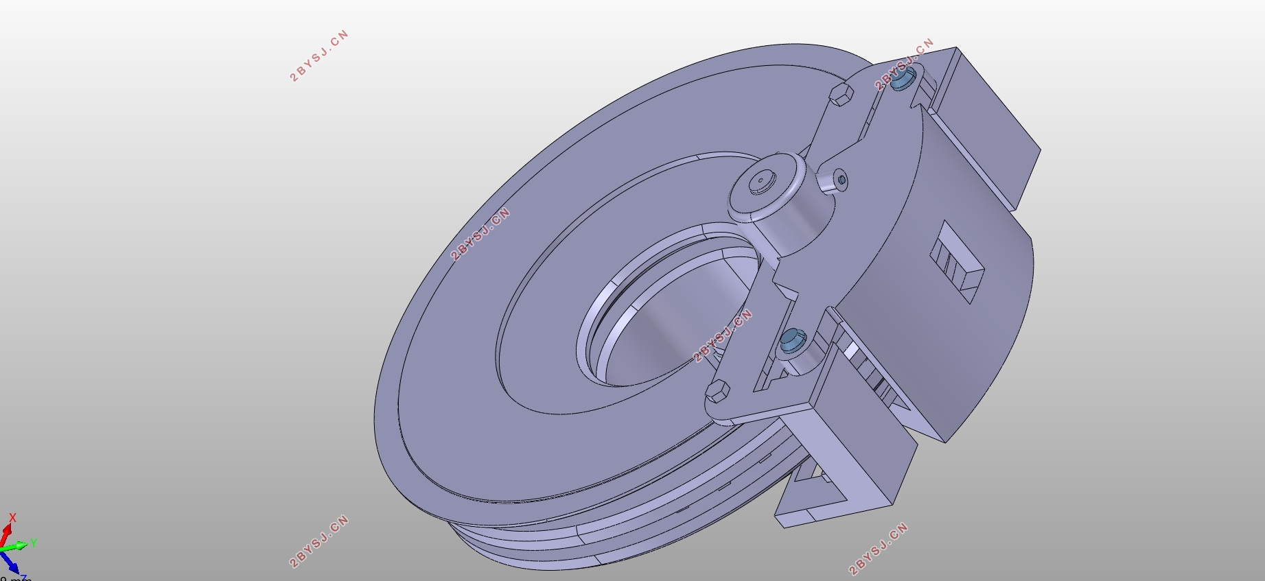
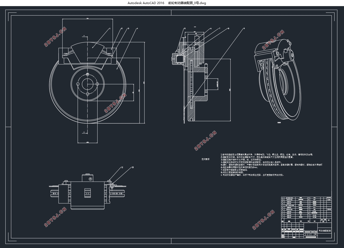
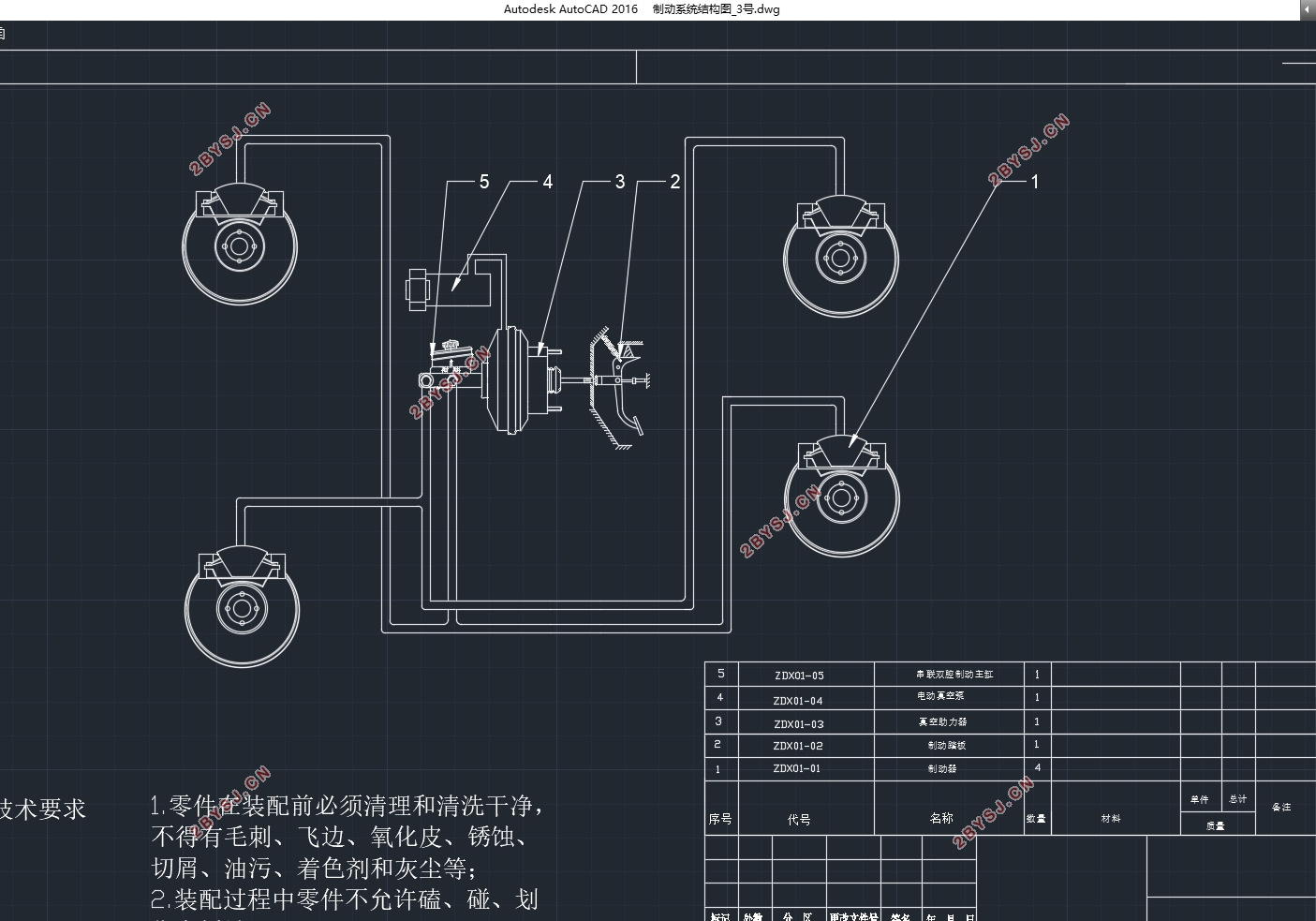
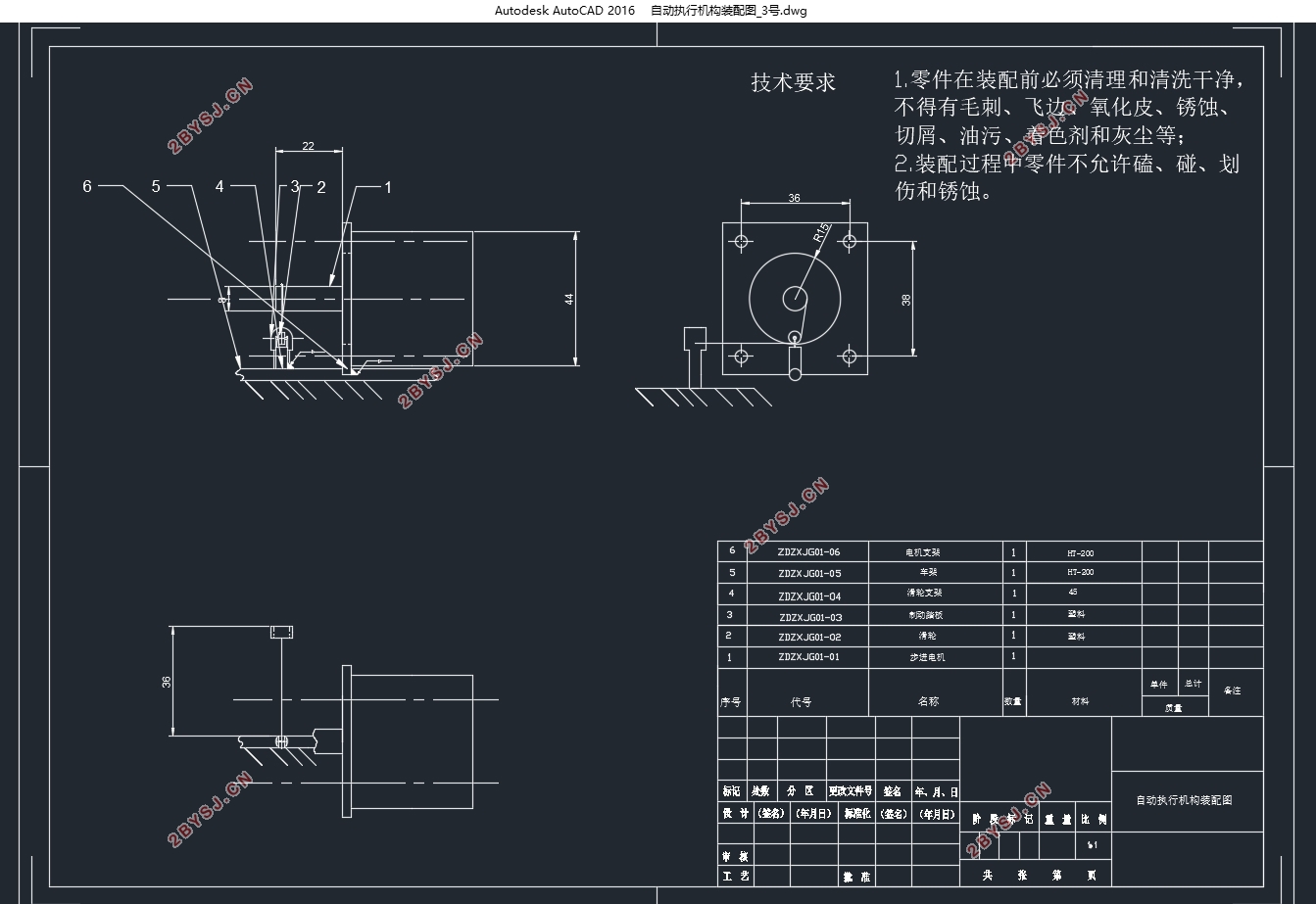
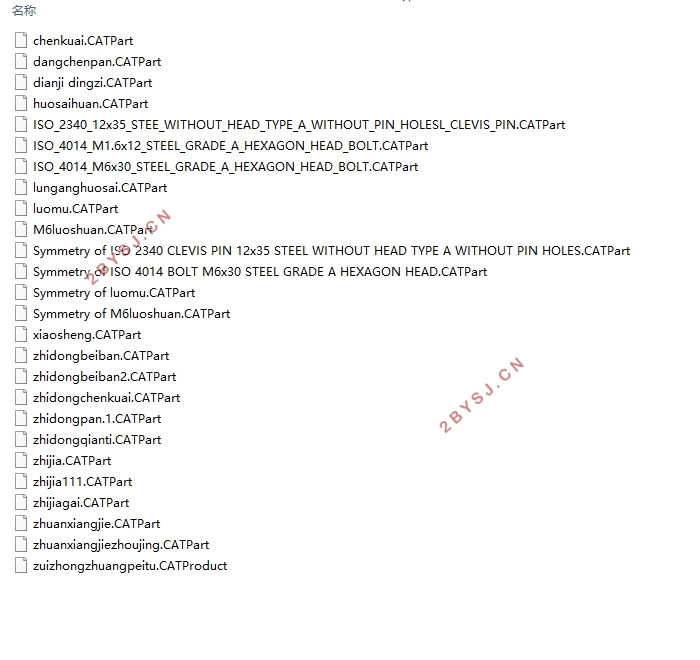
自动驾驶微型纯电动车制动系设计(含CAD零件图装配图,CATIA三维图)(任务书,开题报告,文献摘要,外文翻译,论文说明书13000字,CAD图纸8张,CATIA三维图)
摘 要
随着汽车行业的迅猛发展,汽车的性能相较于以前有了显著的提高。汽车的最高车速也提高了很多,这就使得安全问题愈发严重。汽车最高车速性能的提高对汽车制动也就有了更高的要求,在汽车设计这一大过程中,设计制动系是这其中具有重要地位的一环,汽车制动系的设计对于整车的性能影响有着非常重要的地位,良好的汽车制动系的设计使得汽车会拥有更好的操作稳定性和动力性。汽车制动系的设计需要认真考量。
本文基于已有的一辆纯电动微型车,通过matlab、cad、catia、ansys等软件对其制动系进行设计、选型、优化。首先比较盘式、鼓式制动系的优缺点选择了制动器的类型,接着计算整车基本参数,通过国家法规对制动距离的要求计算出制度减速度,然后计算制动器需要的制动力矩,从而可计算出制动器的结构参数。接着对制动器的各项性能,如比能量耗散率,应急制动力矩,驻车制动力矩做了校核,校核结果满足法规要求。然后针对制动驱动机构进行了设计,如制动主缸、轮缸的尺寸、制动踏板力、制动踏板行程。本文在传统制动系的基础之上,还设计了能够实现其自动制动功能的硬件,采用电机拉线式实现自动制动的功能,设计计算出所需电机的各项性能指标。通过ansys应力分析软件校核,结果理想,故所设计的制动系可以用于该车的制动。
关键词:自动驾驶;微型电动车;制动系设计
Abstract
With the rapid development of the automotive industry, the performance of cars has improved significantly compared with before. The maximum speed of cars has also increased a lot, which makes the safety problem more serious. The improvement of the car's maximum speed performance has a higher requirement for the automobile brake, so the design of the automobile brake system is really a very important module in the automobile design. The design of the automobile brake system has a very important position on the performance of the whole vehicle. The design of a good automobile brake system makes the car hold. an operation stability and power performance. So the design of the automobile brake system needs careful consideration.
Based on the existing pure electric mini car, the braking system is designed, selected and optimized by means of MATLAB, CAD, CATIA and ANSYS software. First, compare the advantages and disadvantages of disc and drum brake system, select the type of brake, then calculate the basic parameters of the whole vehicle, calculate the deceleration of the system by the national regulations and calculate the braking torque, then calculate the structural parameters of the brake. Then the performance of the brake, such as the specific energy dissipation rate, the emergency braking torque and the parking brake moment, were checked, and the check results met the regulatory requirements. Then the brake actuating mechanism is designed, such as brake master cylinder, wheel cylinder size, brake pedal force and brake pedal travel. On the basis of the traditional brake system, this paper also designs the hardware that can realize its automatic braking function. The function of automatic braking is realized by the motor drawing line, and the performance indexes of the required motor are designed and calculated. The ANSYS stress analysis software is checked and the result is ideal. Therefore, the designed brake system can be used for the braking of the vehicle.
Key Words:automatic driving;pure electric mini vehicle;design of braking system
整车基本参数
尺寸参数 长/宽/高(mm) 2300/1700/1540
轴距(mm) 1630
轮距(mm) 1485/1345
质量参数 整备质量(kg) 470
满载总质量(kg) 600
性能参数 最高车速(km/h) 60
最大爬坡度(%) 20
续驶里程(km) 100


目录
第1章 绪论 1
1.1制动系的作用 1
1.2制动系的种类 2
1.3制动系的组成 2
1.4制动系的要求 3
第2章 制动系统技术方案 6
2.1自动制动的功能的实现 6
2.2.1 自动制动系统形式的选择 6
2.2.2 电机形式、参数计算选择 7
2.2 制动回路的选择 7
第3章.制动器的结构种类选择 9
3.1制动器的种类 9
3.2盘式制动器的分类及选择 11
3.3 制动器的选择 13
第4章.整车基本参数 14
4.1 整车基本参数 14
4.2 轮胎半径 14
4.3 空、满载时质心高度及其至前后轴的距离 14
第5章.制动系主要参数选择 15
5.1 制度加速度的计算 15
5.2 同步附着系数及制动力分配系数 15
5.3 前、后轮制动力(矩)计算 16
5.4 制动器结构参数计算 17
5.4.1 制动衬块内外半径的计算 17
5.4.2 制动盘直径D 18
5.4.3 制动盘厚度h 18
5.4.4 全部制动衬块的工作面积 18
5.5 比能量耗散率校核 18
5.6 应急制动力矩校核 19
5.7 驻车制动校核 20
5.8 驻车制动力矩的校核 20
5.9 制动部件有限元应力校核 20
5.10 制动强度与利用附着系数 21
5.11 前后制动效率 22
5.12 满载空载时的I线,β线 23
第6章.制动驱动机构的计算 25
6.1 制动驱动机构的结构型式选择 25
6.2 液压制动驱动机构的设计计算 25
6.2.1 制动轮缸直径 25
6.2.2 制动主缸直径与工作容积 25
6.2.3 制动踏板力与踏板行程 26
第7章 结论 28
致谢 30
附录A matlab程序和运行结果 31