
40+70+40m预应力混凝土连续刚构桥设计(含CAD图)
无需注册登录,支付后按照提示操作即可获取该资料.
40+70+40m预应力混凝土连续刚构桥设计(含CAD图)(任务书,开题报告,外文翻译,论文计算书24000字,CAD图41张)
摘 要
在预应力混凝土结构中,高强钢筋的抗拉性能能够被充分利用,连续刚构桥墩与梁刚性连接,主梁弯矩可以传递到桥墩,分担了全桥的内力,可跨越较大跨度的范围。两者的结合使得整座桥结构性能更加优越。
以九江市八里湖大桥为背景,本次设计的主要过程有拟定上下部结构尺寸、刚构桥模型的建立、主要截面内力的验算以及下部结构的分析。桥梁跨径布置为40+70+40m,荷载等级为公路-Ⅱ级,主梁截面为单箱双室的变截面,施工方法采用悬臂浇筑和边跨部分的满堂支架浇筑,以保证施工阶段通航需求。经过模型的运算,来分析恒载和活载下的内力,并进行预应力损失和各类次内力的验算,以及主要截面应力和抗裂性验算。另外,下部结构设计验算了桥墩及桩基础的承载能力,确保全桥结构的稳定性。
关键词:预应力混凝土;连续刚构桥;Midas建模;上部结构;下部结构
Abstract
In the prestressed concrete structure, the tensile properties of high-strength steel can be fully utilized. Continuous rigid frame piers are rigidly connected with the beam. The main beam bending moments can be transmitted to the piers, sharing the internal forces of the full bridge, and can span the span of larger spans. . The combination of the two makes the entire bridge structural performance more superior.
Taking the Bali Lake Bridge in Jiujiang City as the background, the main processes of this design include the establishment of the upper and lower structural dimensions, the establishment of a rigid-frame bridge model, the verification of the main section internal forces, and the analysis of the substructure.The span of the bridge is 40+70+40m, the load level is Grade II, and the cross-section of the main girder is a single-chamber double-chamber variable section. The construction method adopts the cantilever cast, and the side span part adopts the construction method of full-house bracket pouring,to ensure the navigation requirements during the construction phase.Through the calculation of the model, the internal forces under dead load and live load are analyzed, and the loss of prestress and the verification of various secondary forces are performed, along with the calculation of the main section stress and crack resistance.In addition, the lower structural design is designed to verify the bearing capacity of the piers and pile foundations to ensure the stability of the full-bridge structure.
Key Words:Prestressed Concrete;Continuous Rigid Frame Bridge; Midas modeling; superstructure; substructure
技术标准
(1)道路等级: 城市Ⅱ级支路
(2)设计车速: 30km/h
(3)荷载标准: 公路—Ⅱ级,人群荷载3.45kN/m2;
(4)桥梁设计基准期:100年
(5)结构设计安全等级:一级
(6)抗震设防标准:地震基本烈度6度,按7度设防,地震动峰值加速度0.05g;
(7)设计洪水位:+18.97m(50年一遇水位);
(8)通航等级:VI级,20(净宽)×4.5m(净高);
(9)坐标系统:北京54坐标系
(10)高程系统:1956年黄海高程

目录
第1章 绪论 1
1.1预应力连续刚构桥概述 1
1.2桥型比选原则 2
1.3连续梁桥与刚构桥的比选 2
1.4施工方法的选择 3
第2章 桥梁结构尺寸及设计资料 4
2.1基本资料 4
2.1.1 地形地貌 4
2.1.2 气象 4
2.1.3 水文 4
2.2 工程地质条件 4
2.2.1地层岩性及工程性能 4
2.2.2工程区域岩土体物理力学特性 5
2.2.3 地震 5
2.2.4 工程地质条件评价 5
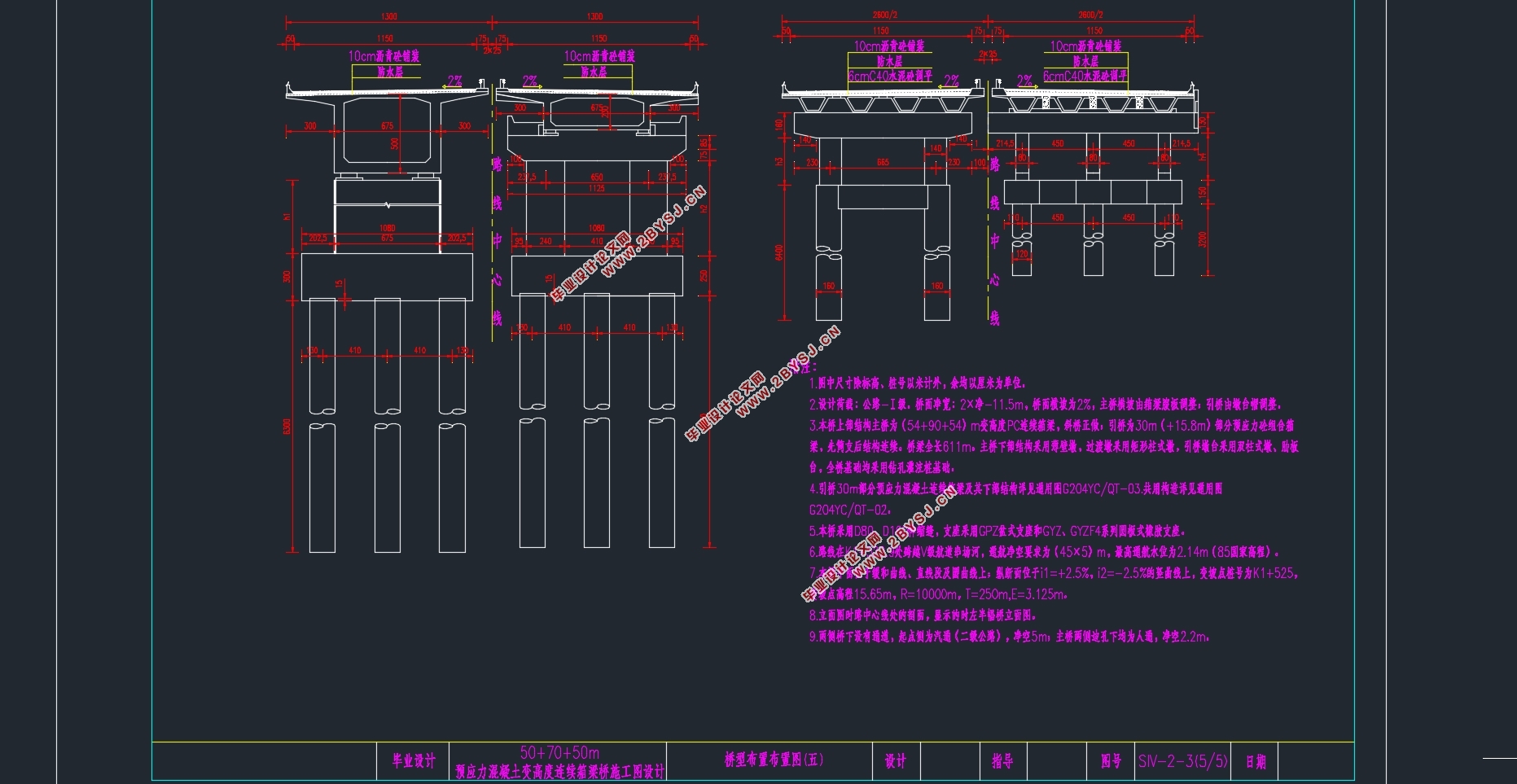
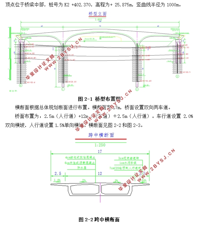
2.3桥型布置 5
2.4桥梁结构尺寸 7
2.4.1主梁结构 7
2.4.2墩台及基础 8
2.5技术标注及规范 8
2.6技术标准 9
2.7建筑材料 9
2.8施工方案 9
第3章 连续刚构桥模型建立及内力分析 12
3.1模型建立步骤 12
3.1.1基本参数的设定 12
3.1.2截面的导入 12
3.1.3整体单元的建立 15
3.1.4施工阶段的划分 16
3.1.5边界约束条件 17
3.1.6荷载类型输入 18
3.2模型分析 19
3.2.1恒载的计算分析 19
3.2.2活载的分析验算 22
3.2.3内力效应组合 25
第4章 预应力钢束设计 30
4.1预应力钢束面积的估算 30
4.2预应力钢束布置 32
4.2.1 钢束布置构造要求 32
4.2.2 钢束布置原则 32
4.2.2 钢束形状 33
4.3普通钢筋估算与布置 35
4.4预应力损失分析 38
第5章 次内力的分析计算 42
5.1预应力次内力 42
5.2混凝土收缩次内力 43
5.3混凝土徐变次内力 43
5.4温度次内力 44
5.5支座沉降次内力 45
第6章 主梁截面验算 47
6.1使用阶段正截面抗裂验算 47
6.2使用阶段斜截面抗裂验算 48
6.3使用阶段正截面压应力验算 49
6.4使用阶段斜截面压应力验算 50
6.5使用阶段斜截面抗弯验算 51
6.6施工阶段法向压应力验算 52
第7章 下部构造的设计与验算 55
7.1桥墩细部尺寸 55
7.2桥墩的正截面承载力验算 57
7.3桥台的设计 58
7.3.1 桥台的细部构造 58
7.3.2 桥台的配筋及验算 59
7.4桩基础设计 61
7.4.1桩基所受荷载 61
7.4.2桩长及承载力计算 61
7.4.2桩基础截面内力 62
7.4.3桩基础截面配筋及强度验算 63
参考文献 67
致谢 68