
武汉某33+56+33m连续箱梁桥结构设计(含CAD图)
无需注册登录,支付后按照提示操作即可获取该资料.
武汉某33+56+33m连续箱梁桥结构设计(含CAD图)(任务书,开题报告,外文翻译,论文计算书25000字,CAD图24张)
摘 要
随着当今社会的不断发展,快节奏的生活对交通网络的改变有着重大的影响,构建快捷、高效、便利的交通网络成为了影响现代城市经济区域模块发展的重要因素之一。梁桥类桥梁因其实用性被广泛使用,其中连续梁桥又因其接缝少、行车平顺、刚度好等优点,被广泛应用于横跨江河等高速公路的衔接中。
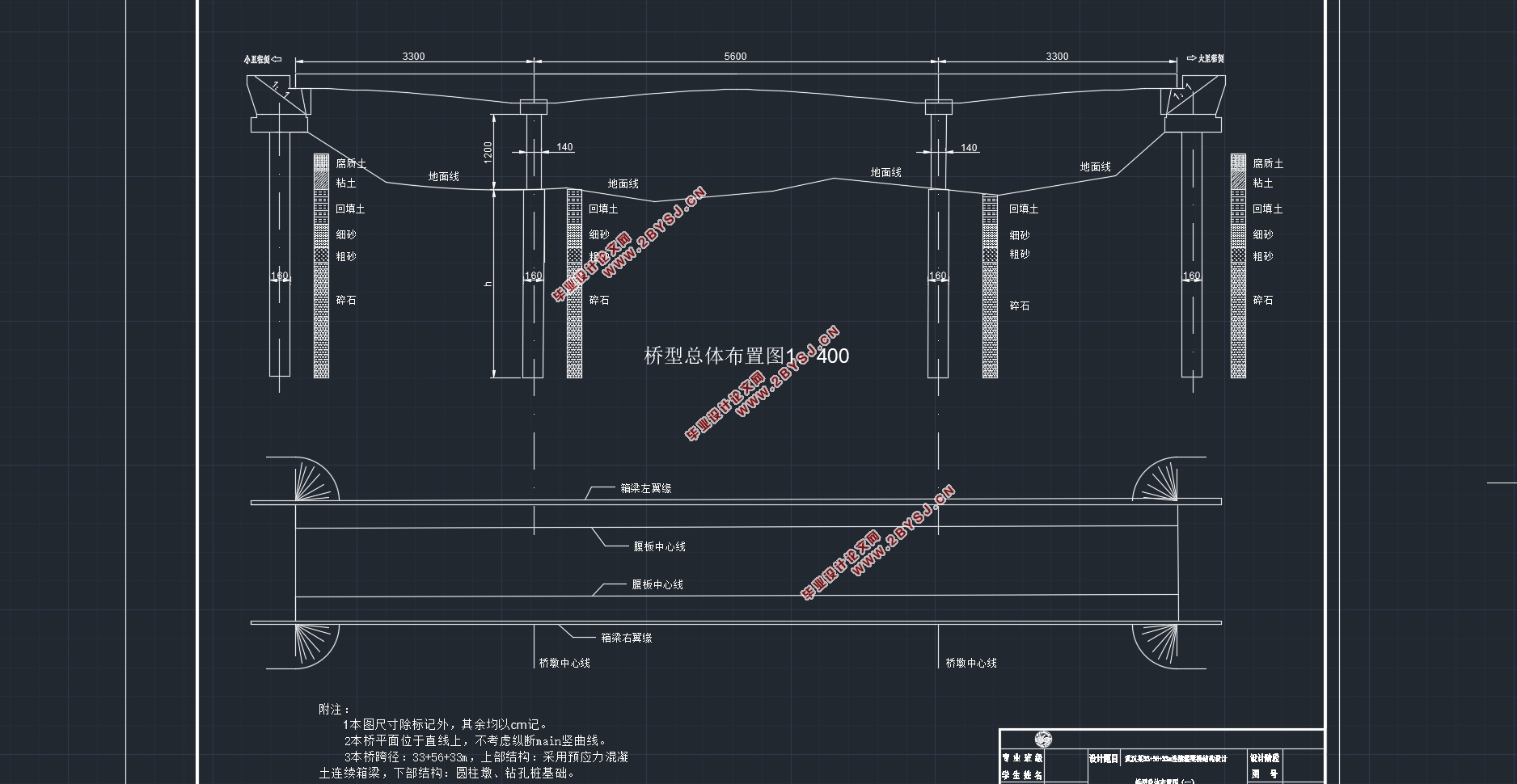
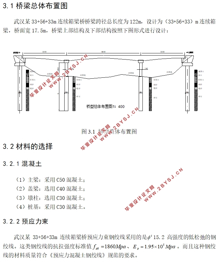
本次毕业设计所设计的桥梁即为跨度为(33+56+33)m的预应力混凝土连续箱梁桥,采用的是2m~4m的变梁高,机动车车道荷载等级为公路Ⅰ级。桥梁宽度共计17.5m,其中,两侧防撞墙均为0.5m,中间隔离带为1.5m,双向共四个3.75m的机动车道。本次设计的连续箱梁桥横截面选用单箱双室截面。整个连续箱梁桥主梁的施工方法采用满堂支架法。整个模型的构建及数据提取使用Midas软件进行。
本次毕业设计的主要假设及条件为:上部连续箱梁结构采用C50预应力混凝土,盖梁及墩柱分别采用C40、C30现浇钢筋混凝土,假设地下水、地表水及空气对桥梁中的钢筋无腐蚀作用,其他参数需要自行拟定进行建模和计算。
关键词:连续箱梁桥;Midas建模;预应力混凝土;满堂支架
Abstract
With the continuous development of society today, the fast-paced life has a significant impact on the changes in the transportation network. The construction of a fast, efficient, and convenient transportation network has become one of the important factors affecting the development of modern urban economic regional modules. Girder bridges are widely used due to their practicability. Among them, continuous girder bridges are widely used in the connection of highways across rivers and other highways due to their advantages of less joints, smooth running, and good rigidity.
The bridge designed for this graduation project is a prestressed concrete continuous girder bridge spanning (33+56+33)m, with a variable beam height of 2m~4m, and the lane load rating of the motor vehicle is Grade I of the highway. The total width of the bridge is 17.5m, of which the anti-collision walls on both sides are 0.5m, the intermediate isolation zone is 1.5m, and there are a total of 4.75m motorway lanes. The cross section of the continuous box girder bridge designed this time is selected from the single-chamber double-chambered section. The construction method of the main girder of the whole continuous box girder bridge adopts full hall bracket method. The entire model was built and data was extracted using Midas software.
The main assumptions and conditions of this graduation project are: C50 prestressed concrete is used for the upper continuous box girder structure, and C40 and C30 cast-in-place reinforced concrete are used for the cap beam and pier column respectively. It is assumed that groundwater, surface water and air have no corrosion effect on the steel bars in the bridge. Other parameters need to be self-developed for modeling and calculation.
Key words: Continuous box girder bridge; Midas modeling; Prestressed concrete; Full house bracket
2.1设计基准
(1)设计荷载:机动车道荷载等级为公路-Ⅰ级;
(2)桥面宽度:本次设计是采用双向四车道,桥面宽度为17.5,两侧防撞墙为0.5m,中央隔离带为1.5m,双向四个3.75m的机动车道;
(3)桥梁结构:为33+56+33m的连续箱梁结构。
2.2设计资料
(1)上部结构:采用C50预应力混凝土连续箱梁;
(2)墩柱:墩柱采用C30现浇钢筋混凝土;
(3)水文地质:地下水及地表水对混凝土结构、钢筋混凝土结构中钢筋无腐蚀性;
(4)其它:地震按动峰值加速度0.05g进行设防,其它自己拟定。
目 录
第1章 绪论 1
1.1 研究背景及意义 1
1.1.1研究背景 1
1.1.2研究意义 2
1.2研究思路及框架 2
第2章 设计内容 4
2.1设计基准 4
2.2设计资料 4
2.3设计内容 4
第3章 桥梁的方案设计 5
3.1桥梁总体布置图 5
3.2材料的选择 5
3.2.1 混凝土 5
3.2.2 预应力束 5
3.2.3 普通钢筋 5
3.2.4锚具及各类材料 6
3.3桥梁主梁的整体设计 6
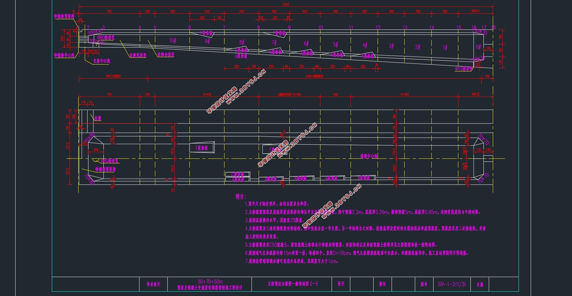
3.3.1 主梁截面设计 6
3.3.2 主梁梁高设计 6
3.3.3 主梁横截面尺寸的拟定 6
3.4施工方法 8
3.5桥面构造设计 8
第4章 Midas建模 9
4.1单位系设置 9
4.2定义材料及主梁截面设置 9
4.2.1 定义材料 9
4.2.2 定义截面 10
4.2.3 变截面的定义 11
4.3Midas结构模型建立 12
4.3.1节点和单元的生成 12
4.3.2定义变截面组 13
4.3.3结构组的定义 14
4.3.4时间依存材料特性的定义 14
4.3.5定义边界条件 15
4.3.6荷载组和钢束组的划分 15
4.3.7静力荷载工况的定义 15
4.3.8定义移动荷载工况 17
4.3.9 预应力钢束的定义 18
4.3.10 定义施工阶段 21
4.4 Midas计算 21
4.4.1荷载组合 21
4.4.2模型结果内力图 22
4.5 运行PSC设计 24
第5章 主梁内力计算 26
5.1一期恒载计算 26
5.2二期恒载内力 26
5.3汽车荷载作用效应计算 27
5.3.1 冲击系数和折减系数 27
5.3.2汽车活载效应计算 29
5.4内力组合 37
5.4.1按承载能力极限状态设计 37
5.4.2按正常使用极限状态设计 37
第6章 钢筋的估算及其布置 38
6.1预应力钢束的估算及其布置 38
6.1.2预应力钢束的估算 38
6.1.3 钢束布置 39
6.2非预应力钢筋的布置 41
6.2.1纵向钢筋 41
6.2.2箍筋布置 41
第7章 钢束预应力损失计算结果 42
7.1基本理论 42
7.2预应力损失计算方法 42
7.3 钢束的预应力损失 43
第8章 Midas验算结果 45
8.1使用阶段正截面抗弯验算 45
8.2使用阶段正截面压应力验算 46
8.3主梁使用阶段正截面抗裂验算 47
8.4受拉区钢筋拉应力验算 47
第9章 盖梁的设计与验算 49
9.1盖梁内力计算 49
9.2盖梁配筋 51
9.2.1弯矩作用下盖梁正截面配筋计算 51
9.2.2剪力作用下的截面配筋计算 52
9.3截面抗裂验算 52
第10章 墩柱的设计与验算 53
10.1荷载计算 53
10.1.2作用于墩柱最大外力 53
10.2墩柱配筋计算 54
10.3墩柱验算 54
第11章 桩基的设计与验算 56
11.1荷载计算 56
11.2桩长计算 56
11.3桩基的内力计算 57
11.3.1桩的计算宽度 57
11.3.2桩的变形系数 57
11.3.3最大冲刷线处桩上外力计算 58
11.3.4桩顶纵向水平位移验算 58
11.4桩基配筋计算及桩身材料截面强度验算 59
参考文献 62
附 表 63
致 谢 102