
广东乐山开发区办公楼给排水设计(含CAD图)
无需注册登录,支付后按照提示操作即可获取该资料.
广东乐山开发区办公楼给排水设计(含CAD图)(任务书,开题报告,外文翻译,论文说明书20000字,CAD图11张)
摘 要
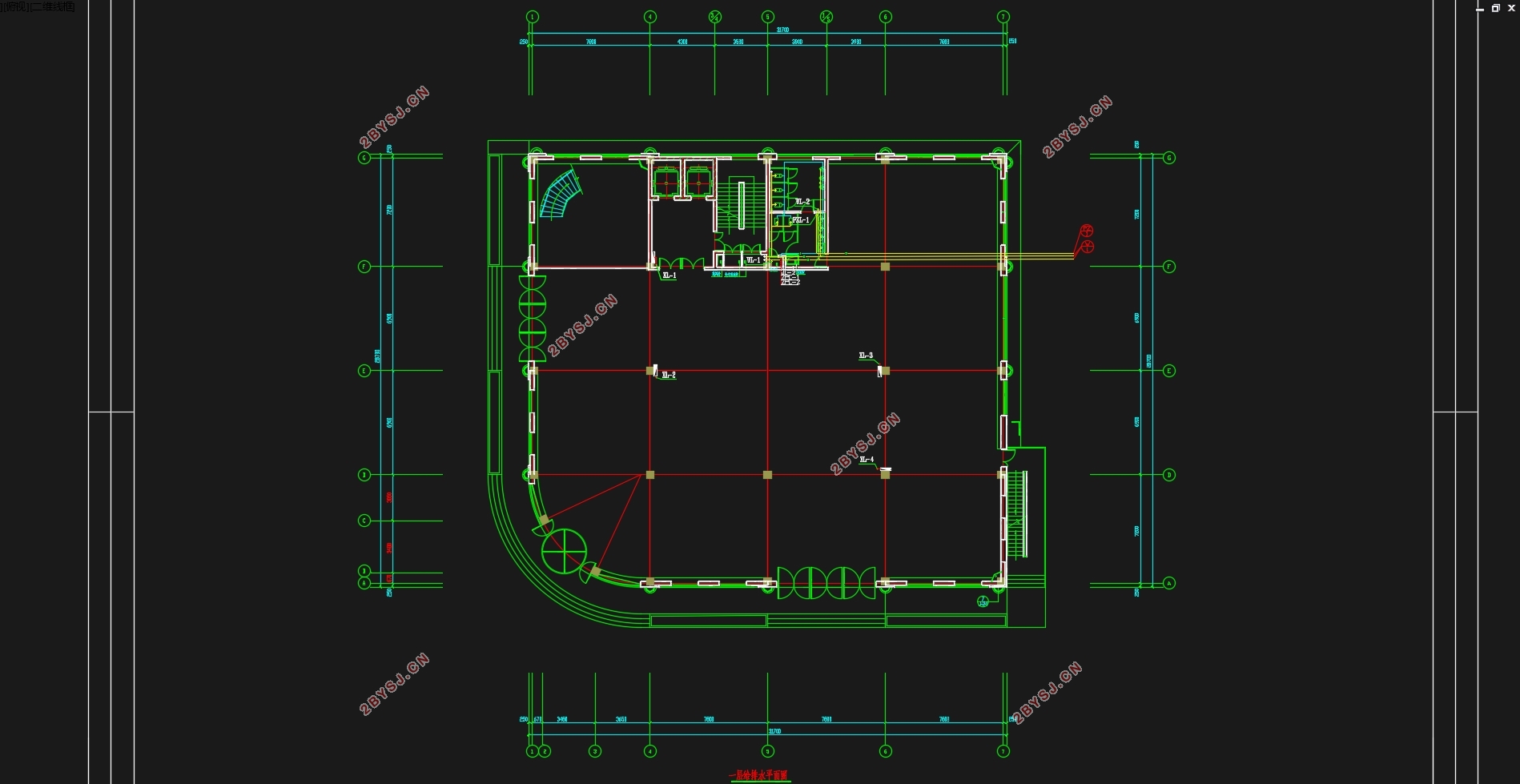
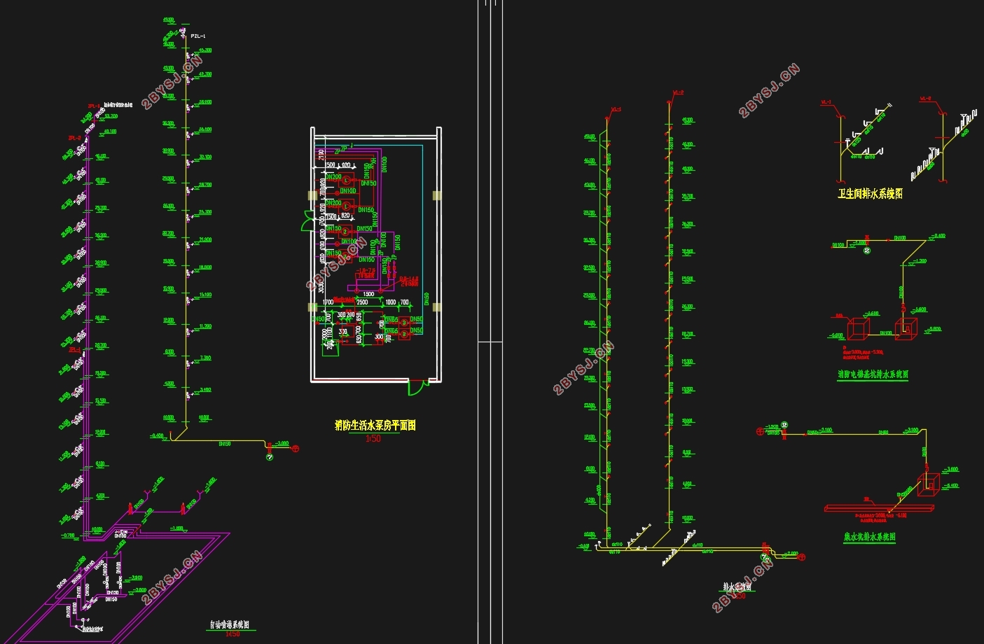
给水系统采取垂直分区并联给水的方式,从市政管网以DN70的管道接水进入建筑,其中负一层至地上四层由市政管网直供,五层至十四层由变频加压供水设备供水。建筑内排水采用污废合流制,室外也是污废合流制,直接排入市政污水管网,排水立管采用专用的通气立管,形成双管制排水系统,其中地上一层单独排水,二至十四层集中排水。地下室排水经排水沟汇集排至集水坑,经潜污泵提升排至检查井。雨水排水系统采用重力流系统,采用外排水体制,顶层屋面雨水经雨水立管排至一层雨水井收集然后排入市政雨水管网。建筑内消防及喷淋在火灾前10min用水由屋面消防水箱提供,取有效容积为18m3,后期灭火用水由地下一层的消防水池提供,其有效容积为246m3。
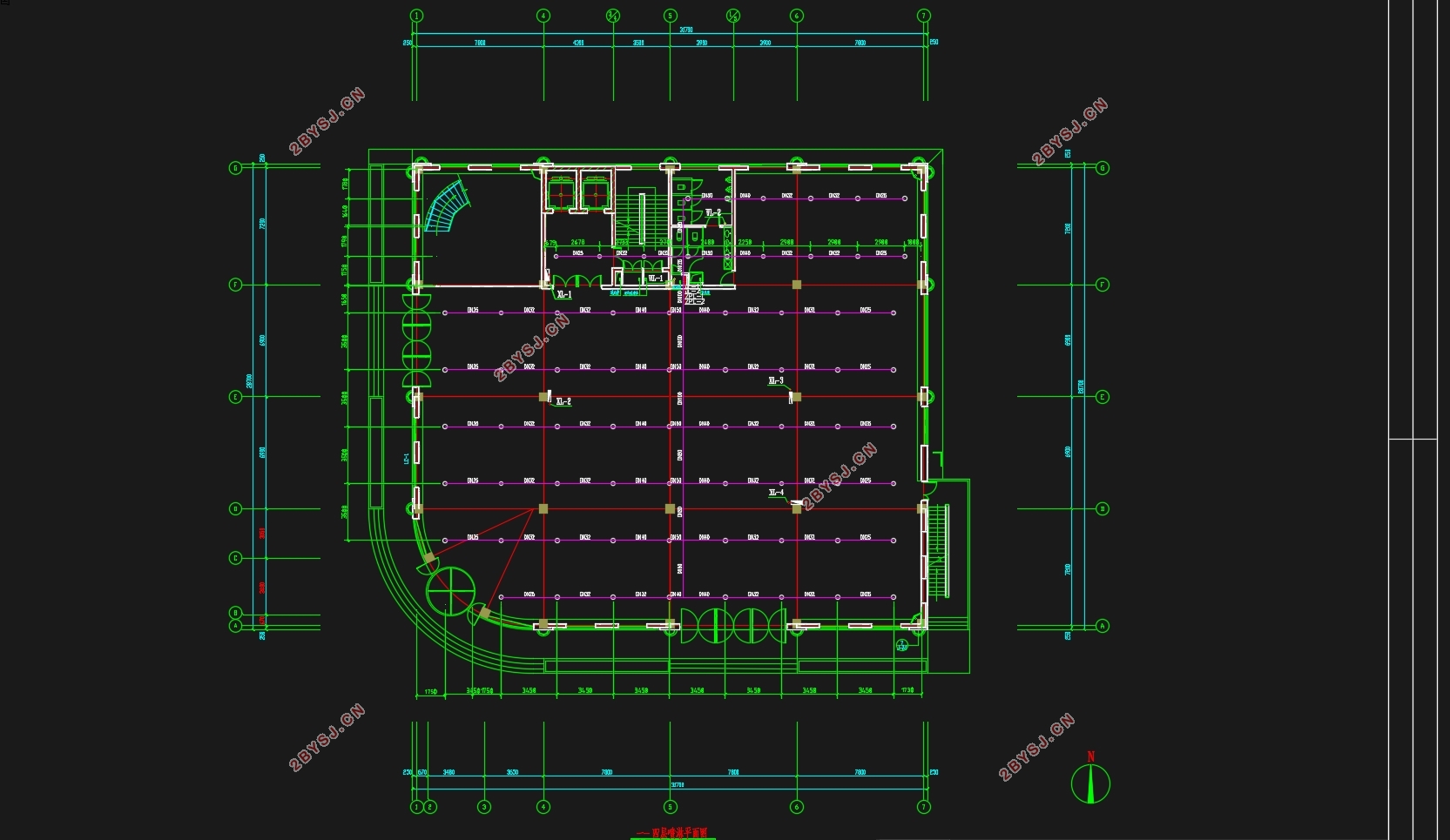
根据查阅规范可知,本建筑属于二类高层民用建筑,耐火等级为二级,室内消火栓用水量20L/s,火灾延续时间2h。消火栓充实水柱高度12m,水龙带长度25m,消防立管管径为DN100。在屋顶层设试验消火栓一个,每个室内消火栓箱内均设有远距离启动消防泵的按钮。根据查阅规范可知,本建筑地上部分为中危Ⅰ级,整个喷淋系统分为两个区,负一至七层为低区,八至十四层为高区。该建筑采用湿式自动喷水灭火系统,喷淋系统设计流量20.8L/s,实际流量为23.23L/s。报警阀设于地下室泵房内,各层均设水流指示器、信号阀和末端试水装置,其信号均送入消防控制中心进行处理。
关键词:给水系统、排水系统、消火栓系统、自动喷水灭火系统、雨水系统
Water supply and drainage design of office building in Leshan Development Zone
Abstract
The water supply system adopts the method of vertical partition and parallel water supply. The water is fed into the building through the DN70 pipeline from the municipal pipe network. The negative one to four floors are directly supplied by the municipal pipe network, and the fifth to fourteenth floors are supplied by the frequency conversion pressure water supply equipment. Water supply. The internal drainage of the building adopts the combined wastewater and waste system, and the outdoor one is also the waste and waste combined system. It is directly discharged into the municipal sewage pipeline network. The drainage riser adopts a special ventilation riser to form a double-controlled drainage system, in which the ground floor is separated by a separate drainage, and two to ten. Four layers of concentrated drainage. The drainage of the basement is drained to the sump through the drainage ditch and lifted by the submersible sewage pump to the inspection well. The rainwater drainage system uses a gravity flow system and uses an external drainage system. Rainwater from the top-level roof is discharged through a rainwater riser to a layer of rainwater wells and then discharged into a municipal stormwater pipe network. The fire and shower in the building shall be provided by the roof fire-fighting water tank 10 min before the fire. The effective volume shall be 18m3. The fire extinguishing water in the later period shall be provided by the fire-fighting pool on the ground floor and the effective volume shall be 246m3.
According to the reference specification, this building belongs to the second category of high-rise civil buildings, the fire resistance rating is two, the indoor fire hydrant water consumption is 20L/s, and the fire duration is 2h. The fire hydrant is full of water column height of 12m, the length of the hose is 25m, and the diameter of the fire riser pipe is DN100. One test fire hydrant is provided on the roof layer, and each indoor fire hydrant box is provided with a button for remotely starting the fire pump. According to the reference specification, the above-ground part of the
building is classified as medium-risk class I. The entire sprinkler system is divided into two areas, the negative one to seven layers are the low areas, and the eight to fourteen layers are the high areas. The building uses a wet sprinkler system. The design flow of the sprinkler system is 20.8L/s. The actual flow rate is 23.23L/s. The alarm valve is located in the pump room in the basement. Each floor is equipped with a water flow indicator, a signal valve and an end water test device. The signals are sent to the fire control center for processing.
Keywords: water supply system, drainage system, hydrant system, automatic sprinkler system, rainwater system
目 录
摘 要 I
Abstract II
第一章 给水系统设计说明 1
1.1给水系统组成 1
1.1.1 给水方式对比 1
1.1.2方案选择依据 3
1.2给水系统组成 3
1.3给水管道的布置与敷设 3
第二章 室内排水系统设计说明 5
2.1排水系统选择 5
2.2 排水系统的组成 5
2.3排水管道安装要求 5
第三章 雨水系统设计说明 7
3.1雨水排水系统的选择 7
3.2雨水排水系统的组成 7
3.3雨水管道的敷设与布置 7
第四章 消防系统设计说明 8
4.1室内消火栓系统 8
4.1.1室内消火栓系统的选择 8
4.1.2系统组成 9
4.1.3设备及构筑物 9
4.1.4消火栓的安装 9
4.2自动喷淋系统 9
4.2.1室内自动喷水灭火系统的选择 9
4.2.2系统组成 10
4.2.3喷头的选择与布置 10
4.2.4设备及构筑物 11
4.2.5喷淋系统的安装 11
第五章 给水系统设计计算 12
5.1用水定额及用水量 12
5.2给水方式 12
5.3低位水池尺寸设计 13
5.4 生活给水系统水力计算 14
5.4.1设计秒流量的计算 14
5.4.2市政直供部分水力计算 15
5.4.3变频恒压供水设备部分水力计算 19
5.5水表的选择 21
5.5.1总水表的选择 22
5.5.2分水表的选择 22
5.6市政直供部分校核 23
5.7增压供水设备选型 23
5.7.1高区给水系统所需压力 23
5.7.2增压设备 24
5.7.3减压阀的设置 25
第六章 室内排水系统设计计算 27
6.1排水体制及排水方式 27
6.2排水系统水力计算 27
6.2.1排水横支管水力计算 27
6.2.2排水立管水力计算 31
6.2.3排水通气立管的选用 32
6.2.4排水横干管水力计算 33
6.3集水坑及提升泵计算选型 33
6.3.1消防电梯集水坑及提升泵计算选型 33
6.3.2水泵房集水坑及提升泵计算选型 34
第七章 雨水排水系统设计计算 35
7.1屋面雨水排水方式 35
7.2降雨强度 35
7.3汇水面积 35
7.4设计秒流量 36
7.4.1建筑屋顶汇水面积的划分 36
7.5雨水斗选用 37
7.6连接管选用 37
7.7溢流口排水量 38
7.8立管选用 38
7.9排出管计算 39
第八章 消火栓给水系统设计计算 40
8.1消防水池 40
8.1.1消防水池的设置 40
8.1.2体积计算 40
8.2屋顶消防水箱 41
8.3消火栓保护半径 42
8.4消火栓布置间距 43
8.5消火栓的确定 43
8.6消火栓的水力计算 44
8.7水泵接合器选定 46
8.8消火栓减压计算 46
第九章 自动喷水灭火系统设计计算 49
9.1自动喷淋灭火系统的基本数据 49
9.2管道与报警阀布置 49
9.3喷头的选用与布置 49
9.4系统的设计流量 49
9.5水力计算(特性系数法) 50
9.5.1 高区喷淋水力计算 51
9.5.3 系统水力计算 57
9.6 增压设备 58
9.7 水泵接合器 58
9.8喷淋减压孔板计算 58
参考文献 61
结语 62
谢辞 63