
某公寓式酒店给排水工程设计(含CAD图)
无需注册登录,支付后按照提示操作即可获取该资料.
某公寓式酒店给排水工程设计(含CAD图)(任务书,开题报告,外文翻译,论文计算书41000字,CAD图30张)
摘 要
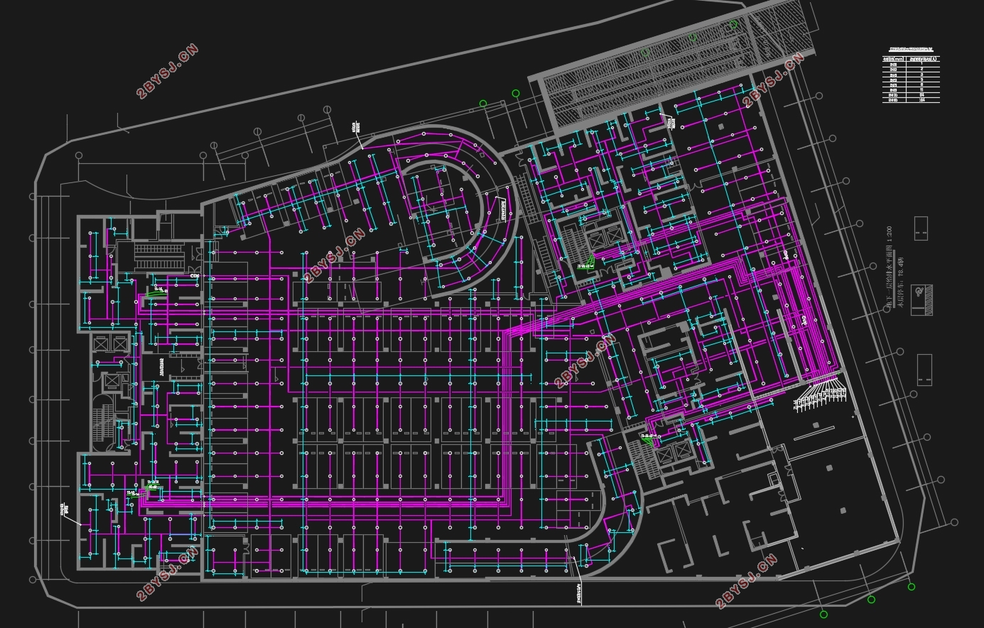
本设计一层至地上三层为市政管网直供,四至三十三层为水泵供水的给水方式。直供部分从市政给水管网接2根DN50的引入管入A座一根DN70的管进B座,另两根DN150的引入管接至地下的生活水池和消防水池。生活水池为不锈钢生活水箱,消防水池采用砖砌混凝土结构,放置地下一层。排水采用生活污、废水合流制,通气管均采用专用通气立管通气。泵房排水槽经汇集排至地下一层集水坑,经潜污泵提升排至检查井后排入市政排水管。建筑四层以上的生活污水管在三层吊顶内,将各单元生活污水管适当汇集转换到排水立管后排出室外。屋面雨水经屋面雨水斗收集后由雨水管排至地面作散水。
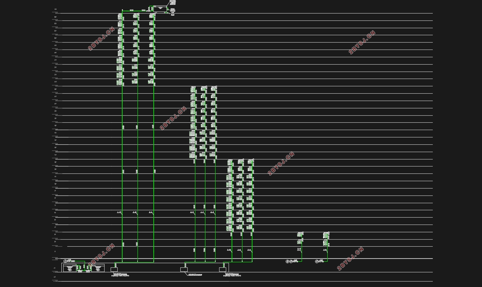
根据规范,该建筑为一类建筑,属中危Ⅰ级。室内消防流量40L/s。充实水柱取12m,水龙带长度取25m,水枪喷嘴流量5.2L/s,消防立管管径为DN100、DN150。在顶层设试验消火栓一个,每个室内消火栓箱内均设有远距离启动消防泵的按钮。
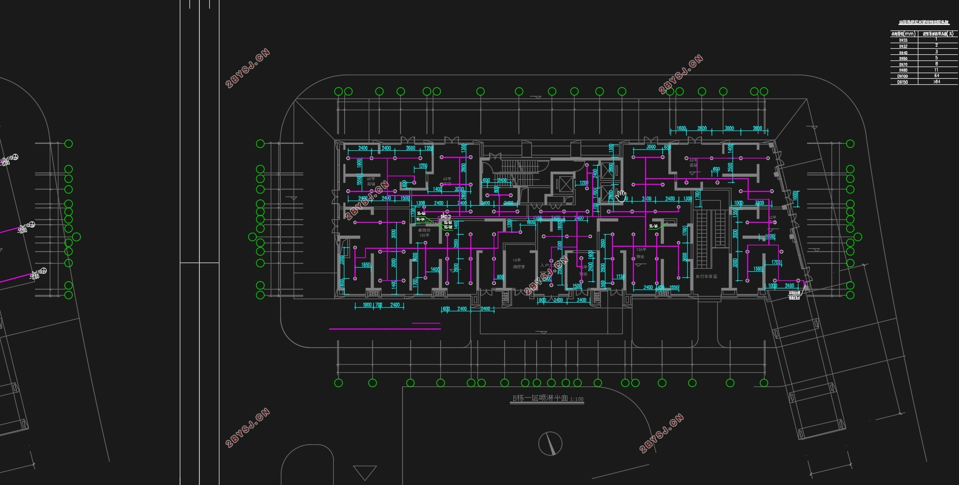
该建筑采用湿式自动喷淋灭火系统,报警阀设于地下一层,各层均设水流指示器和信号阀,其信号均送入消防控制中心进行处理。各层均采用自动喷淋系统,地下一至三层采用直立式喷头。各层均设末端试压装置以及放空管。本工程的自动喷水灭火系统分A座分3个区,B座分4个区。屋顶水箱为36立方米,贮存有10min自动喷水灭火系统、室内消火栓系统用水量。自动喷水灭火系统和消火栓系统的初期灭火由水箱供水,后期供水由地下室的消防水泵和自喷泵供水,各支管与立管连接处设置减压孔板。
根据重力式雨水系统和虹吸式雨水系统的设计分析及造价对比后,本设计采用重力式屋面雨水排水系统.
本建筑物内对二至三十三层设置集中太阳能供热水,预留室内热水器管道。
关键词:给水系统 排水系统 消火栓系统 自动喷水灭火系统 雨水系统
Abstract
In this design, the first floor to the ground floor is the direct supply of municipal pipe network, and the fourth to thirteenth floors are the water supply methods of water pumps.The direct supply part connects two DN50 inlet pipes from the municipal water supply network into block A, one DN70 pipe into block B, and the other two DN150 inlet pipes into the underground living pool and fire fighting pool.The water tank is stainless steel water tank, and the fire water tank is made of brick and concrete.The drainage is made of domestic sewage and waste water, and the ventilation pipes are made of special ventilation riser.The drainage tank of the pump house is collected and discharged to a water collecting pit on the ground floor, and then it is hoisted and discharged to the back of the inspection well into the municipal drainage pipe by the submersible sewage pump.The domestic sewage pipe with four or more floors in the building is in the ceiling of three floors, and the domestic sewage pipe of each unit is properly collected and converted to the drainage riser and then out of the room.Roof rainwater is collected by roof rain buckets and then discharged to the ground by water mains.
According to the specification, the building to building, belong to the dangerous Ⅰ level.Indoor fire flow 40L/s.Fill the water column with 12m, hose length with 25m, nozzle flow rate of water nozzle with 5.2l /s, pipe diameter of fire riser with DN100 and DN150.A test hydrant is set on the top floor, and a button to start the fire pump at a distance is set in each indoor fire hydrant box.
The building adopts a wet automatic sprinkler fire extinguishing system, and the alarm valve is located on the ground floor. All floors are equipped with water flow indicator and signal valve, and the signals are sent to the fire control center for processing.Automatic sprinkler system is adopted for each floor, and vertical sprinkler head is adopted for one to three floors underground.The terminal pressure test device and air vent pipe are installed on each layer.The automatic sprinkler system of this project is divided into three zones in block A and four zones in block B.The roof water tank is 36 cubic meters, and there is water consumption for living, automatic sprinkler system for 10min and indoor hydrant system.Automatic sprinkler system and fire hydrant system in the early fire extinguishing by water tank water supply, water supply from the basement of the late fire pump and the water injection pump, each branch pipe with vertical pipe joint set decompression orifice plate.
According to the design analysis and cost comparison of gravity rainwater drainage system and siphon rainwater drainage system, this design adopts gravity roof rainwater drainage system.
The building is equipped with concentrated solar heating water on floors 2-3, and indoor water heater pipeline is reserved.
Key words: water supply system, drainage system, hydrant system, automatic sprinkler system, rainwater system
1.1工程概况
本项目为两栋高层公寓楼及地下车库,工程规划用地6506.2m2,总建筑面积60010.5m;其中地上面积45457.2m2,地下14553.4m2。建筑高度为99.35m,地上两栋33层塔楼,东侧沿中央大街设置2层裙房、物业等。主楼地上一层功能为公寓门厅、商业,二至三十三层为酒店式公寓。地下室三层局部设夹层,功能为非机动车库,自走式机动车库,储藏室和设备用房。城市给水管网常年提供可靠水压为0.30MPa,市政管网不允许直接抽水,水质符合饮用水标准。地区最大冰冻深度0.15m。城市排水管网为污、雨分流制排放系统。建筑物污水汇集经化粪池处理后排入城市管网集中送至城区集中污水处理厂,市政排水干管DN400,管底埋深2.5~3.0 m。

计算书目录
摘要 2
Abstract 3
第一章——给排水工程设计任务书 5
1.1工程概况: 5
1.2设计依据: 5
1.3设计内容: 6
1.4设计图纸及要求: 6
1.5设计进度计划: 6
第二章设计说明书 7
2.1建筑给水系统设计 7
2.1.1给水系统选择 7
2.1.2给水系统组成 8
2.1.3给水管道布置与安装 11
2.2建筑排水系统设计 12
2.2.1排水方式选择 12
2.2.2通气管选择 13
2.2.3排水系统的组成 13
2.2.4排水管道及设备安装要求 13
2.2.5关于清扫口、检查口 14
2.3建筑消火栓系统设计 15
2.3.1设计说明 15
2.3.2设计参数 15
2.3.3系统设计 15
2.4建筑自动喷水灭火系统设计 16
2.4.1设计说明 16
2.4.2基本设计数据 16
2.5建筑雨水系统设计 18
2.5.1系统选择 18
2.6各系统管道材料选择 18
第三章 计算说明书 19
3.1给水系统 19
3.1.1室内给水系统计算 19
3.1.2地下室贮水池容积 22
3.1.3水力计算 23
3.1.4地下室加压水泵计算 31
3.2排水系统 32
3.2.1排水立管管径确定 32
3.2.2集水井容积的计算 37
3.2.3化粪池设计计算 37
3.3消火栓系统 38
3.3.1消防水池 38
3.3.2屋顶消防水箱 39
3.3.3消火栓的布置 40
3.3.4水力计算 41
3.3.5增压系统水泵选择 44
3.3.6减压孔板计算 45
3.3.7水泵接合器设置 48
3.4自动喷水灭火系统 48
3.4.1自动喷水灭火系统的基本数据 48
3.4.2喷头的选用与计算 48
3.4.3系统的设计计算 49
3.4.4水力计算 49
3.4.5喷淋系统水泵选择 51
3.5雨水系统 48
3.5.1屋面雨水排水方式 48
3.5.2水力计算 48
3.5.3雨水斗和立管的选用 49
结束语 49
参考文献 53