
数字化管道自动检测装置机械结构设计
无需注册登录,支付后按照提示操作即可获取该资料.
数字化管道自动检测装置机械结构设计(任务书,开题报告,毕业论文说明书21000字,CAD图纸5张)
[摘要] 本文将会提到NDT方式和机器人系统,无损检测机器人已经被证明能够非常有效的检测发电厂水冷壁管的缺陷,该机器人能够从管子底部爬到足够的高度。检测仪器也足够检测通孔(直径大于1.6mm)和墙体缺陷,在完成信号处理和滤波方法后,该仪器还可以完成清洗、修理和一些其他的任务。
根据已有知识经验和面临的实际问题,一种能有效检测管道的自动检测机器人系统问世了,这种自动检测机器人采用的是磁感应技术和超声波方式。利用漏磁技术(MFL)可以检测管道壁的腐蚀和侵蚀,管壁缺陷首先通过磁桥原理检测,然后再用超声波探测质量,磁力传感器是用霍尔元件组合,通过以上原理设计的,检测实验演示了无损检测机器人(NDT),NDT包括锅炉壁清洁器械,支撑和爬行机械的安全装置,检测装置,控制系统和信号处理软件。能够在管道上上下运动,该器械可以检测(大约1.6mm的)孔和壁的缺陷。
[关键词] 水冷壁管;无损检测;磁通;超声波
Digital pipeline automatic detection device of mechanical structure design
[Abstract] The NDT method and robot systemproposed in this paperhas been proved to be efficient in the defects detection located on the fire side of water wall tubes, and the robot can climb the full height of the boiler from the bottom. And the apparatus have been able to test the defect of through hole (bigger than diameter 1.6 mm) and wall loss. After completing the research of the signal processing and filter methodsthe apparatus can be used not only for inspection but for cleaningrepairing and other required tasks.
According to the defect characteristics and the failure mechanismsa inspection robot system was developed to test the tube effectively based on the magnetic flux leakage (MFL) technique and ultrasonic method. Using the magnetic flux leakage technique, the corrosion and erosion on the outer diameter (OD) surface can be inspected. The wall loss can be tested with the magnetic bridge principle firstly, and inspected by ultrasonic probe quantitatively. The magnetic sensor was designed by the principle above-mentioned, and developed with Hall element arrays. The inspection experiment demonstrate that the NDT robot, which includes the furnace wall cleaning apparatusthe adhesion and crawling mechanism and safetythe inspection devicethe control system and the signal processing software, can be driven up and down the tube automatically, and the apparatus was able to test the defect of through hole (bigger than diameter 1.6 mm) and wall loss.
[Key words] boiler water wall tube; nondestructive testing; magnetic flux leakage; ultrasonic.
原始数据:
排管规格:φ63.5×8mm;爬行高度:50m;爬行速度:8—15m/min(可调) ;机身重量:≤15 kg;外形尺寸:≤350×320×240mm(可参照进行适当调整)
主要研究(设计)内容
1)阐述水冷壁管存在的缺陷、水冷壁管检测的现状及主要方法等。
2)管道自动检测装置实现方案设计包括:磁化装置、选择传感器、爬行装置
3)受力分析,包括静态受力分析、磁力分析计算
4)选择电动机,传动比的分配,传动装置的运动和动力参数计算
5)轴的设计计算,包括轴材料的选择,初步估算轴的直径、轴的结构设计、轴的强度验算
6)轴承的选型和校核
7)联接键的选择及校核计算,包括蜗轮与轴连接用键、齿轮与轴连接用键
8)联轴器的选择及校核计算
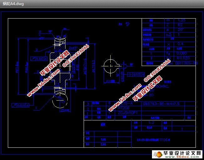
9)蜗轮蜗杆的结构设计,包括选择蜗杆传动类型、选择材料、按齿面接触疲劳强度进行设计、蜗杆与蜗轮的主要参数与几何尺寸、校核齿根弯曲疲劳强度
10)齿轮的设计计算
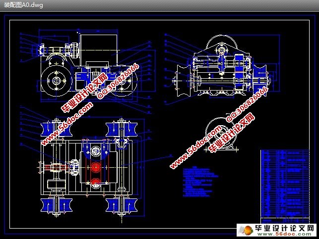
11)爬壁装置的装配图,蜗轮、蜗杆、齿轮、轴等主要零件零件图的绘制
关键问题
(1)电机的功率转速选择与设定
(2)轴的尺寸设定和刚度设定
(3)齿轮尺寸设定和刚度设定
(4)爬行装置的结构设计
目 录
任务书………………………………………………………………………………………I
开题报告………………………………………………………………………………Ⅱ
指导教师审查意见……………………………………………………………………Ⅲ
评阅教师评语…………………………………………..…………………………………Ⅳ
答辩会议记录……………………………………………..………………………………Ⅴ
中文摘要……………………………..……………………………………………………Ⅵ
外文摘要 …………………………………………………………………………………Ⅶ
前 言………………………………………………………………………………………1
1 绪论………………………………………………………………………………………2
1.1 研究的目的和意义………………………………………………………………..2
1.2 水冷壁管存在的缺陷……………………………………………………………..2
1.3 水冷壁管检测的现状及主要方法………………………………………………..3
2 管道自动检测装置实现方案……………………………………………………………6
2.1 磁化装置…………………………………………………………………………..6
2.2 选择传感器………………………………………………………………………..7
2.3 爬行装置…………………………………………………………………………..7
3 受力分析………………………………………………………………………………..10
3.1 静态受力分析……………………………………………………………………10
3.2 运动时的受力分析………………………………………………………………11
3.3磁力分析计算…………………………………………………………………….12
4 选择电动机……………………………………………………………………………..14
5 拟定传动方案…………………………………………………………………………..15
5.1 传动比的分配……………………………………………………………………15
5.2 传动装置的运动和动力参数计算………………………………………………15
6 蜗轮蜗杆的结构设计………………………………………………………………..…17
6.1 选择蜗杆传动类型………………………………………………………………17
6.2 选择材料…………………………………………………………………………17
6.3 按齿面接触疲劳强度进行设计…………………………………………………17
6.4蜗杆与蜗轮的主要参数与几何尺寸…………………………………………….18
6.5 校核齿根弯曲疲劳强度…………………………………………………………18
7 齿轮的设计计算…………………………………………………………………..……20
7.1 选择齿轮类型、精度等级、材料及齿数………………………………………20
7.2按齿面接触强度设计…………………………………………………….………20
7.3 按齿根弯曲强度设计……………………………………………………………21
7.4 几何尺寸计算……………………………………………………………………22
7.5 验算………………………………………………………………………………23
8 轴的设计计算………………………………………………………………………..…24
8.1 选择轴的材料……………………………………………………………………24
8.2 初步估算轴的直径………………………………………………………………24
8.3 轴的结构设计……………………………………………………………………24
8.4 轴的强度验算……………………………………………………………………25
9 轴承的选型和校核………………………………………………………………..……31
9.1 蜗杆轴两端轴承的选型及校核…………………………………………………31
9.2 蜗轮轴两端轴承的选型及校核…………………………………………………32
10 联接键的选择及校核计算……………………………………………………………33
10.1 蜗轮与轴连接用键………………………………………………………..……33
10.2 齿轮与轴连接用键……………………………………………………..………33
11 联轴器的选择及校核计算……………………………………………………………34
12 总结……………………………………………………………………………………35
参考文献………………………………………………………………………………..…36
致 谢……………………………………………………………………………………..37