
�˹��ؽڷ�������������(��CAD���װ��ͼ)
����ע���¼,֧��������ʾ�������ɻ�ȡ������.
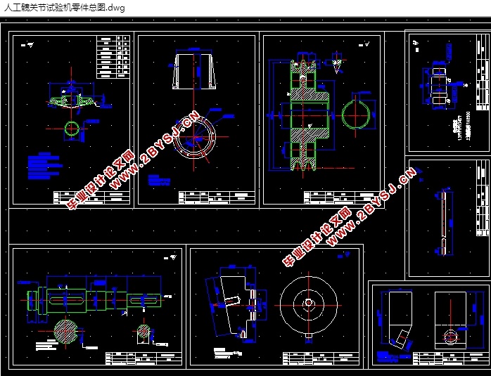
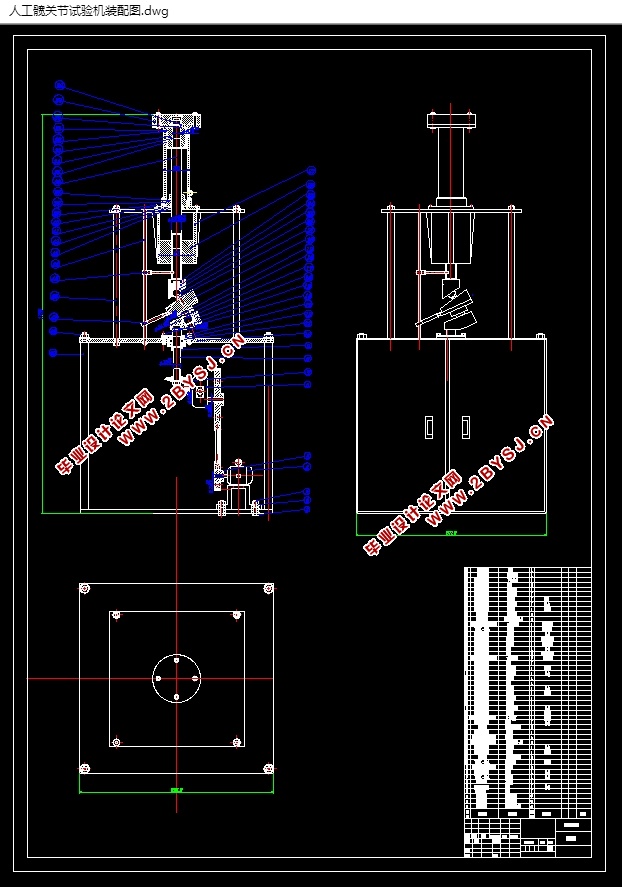
�˹��ؽڷ�������������(��CAD���װ��ͼ)(����˵����15700��,CADͼֽ9��)
DESIGN OF BIONIC TESTING MACHINE FOR ARTIFICIAL JOINTS
ժҪ
�������Ƕ������Źؽ�ģ���������е�������ֵ����ơ����ϸ����ͣ�������������Ѿ��о����ܶ��ֵĹؽڷ�����������豸�����ҷ�չ����ȫ���Ѿ��м�ǧ����ͨ���û������ؽڣ����¿����������ߡ����ʵ����Ĺ���ԭ���ǽ��ɹ�ͷ���žʲ�������������������λ�ð�װ������̨�ϣ�ͨ������װ��ʹ����֮���������˶�������������ʱ���ǵ���Ҫ������ʹ����ʵ���һ������ܹ���ȷģ�������Źؽڵ�ʵ���˶�״�����Դ���ʹ�Լ�����������в�����Ħ��������ĥ����ʽ��ʵ��ʹ����������һ�£��Ӷ�����ȷ���ɿ��ز����˹��ؽڲ��ϵ�����Ħ��ѧ���Բ�������Щ��������Ϊ�ٴ�Ӧ���ṩָ�����������ݡ�
�ؼ��ʣ�������������˵��Źؽڣ�Ħ������
Abstract
This topic is the development of the mechanical transmission part of the human hip joint simulator. In the last century, many countries have studied many kinds of equipment for the bionic test machine of joint. And so far, tens of millions of people in the world have been able to walk normally through replacement of bionic joints in the world. The principle of this experiment machine is to install the specimen of the femoral and acetabular parts on the test bed in the normal position of the body, and make the relative motion between the two. The main factor to be considered in the design of the test machine is that it can correctly simulate the actual movement of the human hip joint in the laboratory environment so that the friction mechanism and wear form produced in the test process are in accordance with the actual conditions, thus the birth of the artificial joint material can be accurately and reliably tested. The tribological properties of these parameters can provide guidance test data for clinical application.
Keywords bionic testing machine human hip joint tribological properties
Ŀ ¼
ժҪ I
Abstract II
1���� 1
1.1 �����Źؽ������豸�ı��� 1
1.2�˹��ؽڷ��������������Ϊֹ���о���� 2
1.3 �����Ƶ���ҪĿ�� 4
2��Ʒ�����ѡ�� 5
2.1 �����Źؽڵ���ɺ��˶��ص� 5
2.1.1 �Źؽڽṹ���˶� 6
2.1.2 �˹����Ƶ��Źؽ���� 6
2.2 ��Ƶķ����������ѡ�� 7
2.3 �����и��������˶����Է��� 10
3 �������ѡ����Ƽ��� 12
3.1ѡ��綯�������� 12
3.2����������� 12
3.3ѡ������������� 15
3.4 ���ֵ���� 16
3.4.1 ���ֵ���Ҫ���γߴ���Ƽ��� 16
3.5 �����������Ľṹ 22
3.5.1 ѡȡ��IJ��� 22
3.5.2 ѡȡ���ë�� 22
3.5.3 ȷ���������Сֱ�� 23
3.5.4 ������ϵĽṹ���� 23
3.6 ��ư���Ľṹ 28
3.6.1����IJ��ϵ�ѡ�� 28
3.6.2�������Сֱ����ѡ����� 28
3.6.3������װ������ 28
3.6.4 ���а����ǿ��У�ˣ�������Ť�ϳ�У�� 29
3.6.5������Բ������е�У�˼��� 30
3.7 ��������ܷ���� 31
���� 34
��л 35
����� 36