
100t/38m机械差动驱动桥式起重机设计(含CAD图)
无需注册登录,支付后按照提示操作即可获取该资料.
100t/38m机械差动驱动桥式起重机设计(含CAD图)(任务书,开题报告,论文说明书14000字,CAD图3张)
摘要
近年来,起重机领域的专家与学者专注于研究如何在不改变桥式起重机起重量的情况下降低其整机的自重,以达到最经济性的效果。国内外的文献中提出的方案大多是通过更换桥架的材料来减轻主梁的自重,取得了一定的进展,但难以进一步突破,要从根本上解决该问题,就要改变传统桥式起重机的结构形式。桥式抓斗卸船机采用牵引式小车的运动方式,极大的降低了主梁的承载,本论文考虑将桥式起重机的小车更换为牵引式,从其上移除起升驱动机构和运行驱动机构,大幅度减轻小车的轮压,从而达到主梁轻量化的目标。
具体内容:
1)确立机械差动驱动的结构形式,详细分析其工作原理,比较其与传统桥式起重机的区别。
2)通过设计参数,确定设计桥式起重机的桥架尺寸。
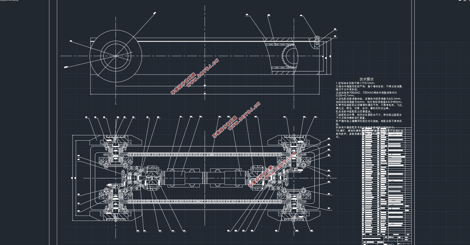
3)完成对起重机小车、大车主要零部件的计算选型。特别是通过机构工作的速度,对机械差动驱动核心部件—行星差动减速器进行设计,确定了其内部齿轮的齿数与模数。
4)利用SolidWorks软件对机械差动驱动机构进行三维建模,并通过Adams软件对该机构进行仿真分析,得出了三种不同工况下各机构的速度、位移曲线。
关键词:机械差动驱动;桥式起重机;总体设计;SolidWorks;Adams
Abstract
In recent years, experts and scholars in the field of cranes have focused on how to reduce the weight of the whole machine without changing the lifting weight of the overhead crane in order to achieve the most economical results. Most of the proposals put forward in domestic and foreign literatures are to reduce the weight of the main beam by replacing the material of the bridge frame, and certain progress has been made, but it is difficult to further break through. To fundamentally solve this problem, we must change the structure of the traditional bridge crane. form. The bridge type grab ship unloader adopts the movement mode of a towing trolley, which greatly reduces the load of the main girder. This paper considers replacing the trolley of a bridge crane with a towing type, and removes the lifting drive mechanism and operation from the bridge crane. The drive mechanism greatly reduces the wheel pressure of the trolley, thereby achieving the goal of lightweighting the main beam.
details:
1)Establish the structural form of mechanical differential drive, analyze its working principle in detail, and compare its difference with traditional bridge cranes.
2)Determine the bridge size of the designed bridge crane through design parameters.
3)Completion of the calculation and selection of the main components of crane trolleys and carts. In particular, by designing the planetary differential speed reducer, which is the core component of mechanical differential drive, through the speed of the work of the mechanism, the number of teeth and the modulus of its internal gear are determined.
4)Using SolidWorks software to carry out three-dimensional modeling of the mechanical differential drive mechanism, and through the Adams software simulation analysis of the mechanism, obtained the speed and displacement curve of each mechanism under three different conditions.
Key word:Mechanical differential drive;Bridge crane;Overall design;SolidWorks;Adams

目录
第1章绪论 1
1.1 课题研究背景及意义 1
1.2 国内外研究现状 1
1.3 差动驱动技术研究 2
1.4 本文完成的主要工作 3
第2章 机械差动驱动结构形式及工作原理 4
2.1 传统桥式起重机结构形式 4
2.2 机械差动桥式起重机结构形式与工作原理 4
第3章 桥架结构的设计 6
3.1 桥架结构的设计计算 6
3.1.1 主梁高度及腹板高度 6
3.1.2 腹板厚度 6
3.1.3 主梁的宽度 6
3.1.4 端梁 6
第4章 小车机构的设计 7
4.1 滑轮组倍率的选择: 7
4.2 钢丝绳的选择 7
4.2.1 钢丝绳结构形式的选择: 7
4.2.2 钢丝绳直径的计算与选用 8
4.3 滑轮的选择 8
4.4 卷筒的选择 8
4.4.1 卷筒的直径 8
4.4.2 卷筒的长度 8
4.4.3 卷筒转速 9
4.4.4 卷筒强度、稳定性校核 9
4.5 小车车轮与轨道的选择及其强度校核 10
4.5.1 车轮的校验计算 11
4.6 运行阻力的计算 11
4.7 选择电动机 11
4.8 电动机校验 13
4.8.1 起升机构电动机校验 13
4.8.2 小车运行机构电动机校验 14
4.9 设计减速器 15
4.10 选择联轴器 17
4.11 选择制动器 18
第5章 大车运行机构的设计 19
5.1 大车运行机构的设计计算 19
5.1.1 大车运行结构的传动方案 19
5.1.2 轮压计算及强度验算 19
5.1.3 运行阻力计算 21
5.1.4 选择电动机 21
5.1.5 选择减速器 22
5.1.6 选择联轴器 22
5.1.7 选择制动器 23
5.1.8 验算与校核 24
5.1.9 打滑计算 26
第6章 机械差动驱动机构三维建模 28
6.1 行星差动减速器建模 28
6.2 其他零部件建模 28
6.3 机械差动驱动机构三维模型 29
第7章 机械差动驱动机构运动学仿真 31
7.1 约束的添加 31
7.2 机构的运动学仿真 32
第8章 环境影响及经济性分析 35
8.1 环境影响分析 35
8.2 经济性分析 35
第9章 总结与展望 36
9.1 全文总结 36
9.2 展望 36
参考文献 38
致谢 40