
60+100+100+60m预应力混凝土刚构连续组合箱梁桥施工图设计(含CAD图)
无需注册登录,支付后按照提示操作即可获取该资料.
60+100+100+60m预应力混凝土刚构连续组合箱梁桥施工图设计(含CAD图)(任务书,开题报告,外文翻译,论文说明书16000字,CAD图7张)
摘要
本次毕业设计题目为60+100+100+60m预应力混凝土刚构连续箱梁桥。刚构连续组合梁桥吸收了连续梁桥与连续刚构桥的优点,适用于跨度大同时桥墩较矮的情况,有效预防了温度内力太大的问题。由于时间和个人能力的限制,这次设计没能进行横向、竖向预应力以及抗震的设计。
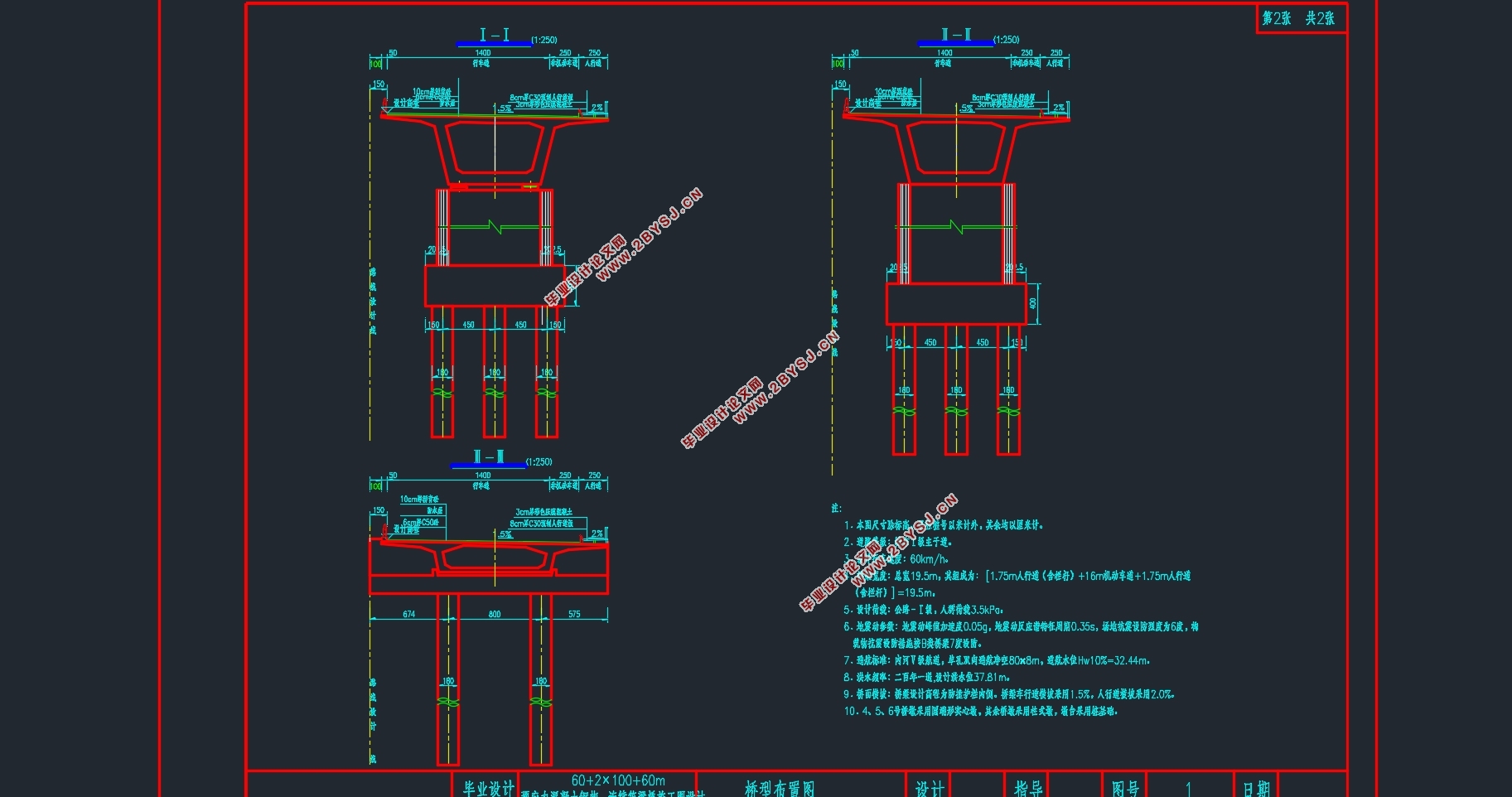
本设计首先根据设计经验及构造要求拟定了主梁的主要构造和相关细部尺寸;考虑到桥梁结构形式,边、中主墩墩身采用圆端形实心桥墩;根据地质情况选用摩擦桩作为基础。
其次确定施工方法,采用篮对称悬浇的施工方法,按三个“T”形同步施工,0号块在主墩施工结束后在支架上现浇,之后对称浇筑1~12号块,边跨在满堂支架上现浇,之后先边跨合拢再进行中跨合拢。
之后,利用MIDAS/CIVIL软件建模,进行结构有限元分析。根据拟定桥梁尺寸建立桥梁基本模型,依次完成内力分析、预应力筋的估算与布置以及截面验算。建模时要考虑混凝土收缩徐变、温度、沉降等因素的影响,进行相关次内力的分析。同时,对行车道板、锚下局部承压、桥墩及基础进行了相应的计算。
经由分析验算表明,本次设计计算方法正确,内力分布合理,达到设计任务的要求。
关键词:刚构连续组合梁桥;MIDAS/CIVIL;悬臂施工;结构分析
Abstract
The title of this graduation project is 60+100+100+60m prestressed concrete rigid frame continuous box girder bridges. The rigid-frame continuous composite girder bridge absorbs the advantages associated with continuous girder bridges and continuous rigid-frame bridges, and is suitable for the case where the spans are large and the bridge piers are short at the same time, effectively preventing excessive internal forces of temperature.
First of all, the main structural elements and detail sizes are designed. In consideration of the bridge structure, the main piers of the sides and the middle main pier adopt solid ends with round ends; the friction piles are selected based on the geological conditions.
Secondly, the construction methodis determined. With domestically-developed basket-mounted symmetric cantilever construction method,according to three “T” simultaneous constructions, block 0 is cast on the support after the construction of the main pier, and the blocks 1 to 12 are symmetrically placed afterwards. The side spans are cast on the full house scaffolding, and then the first span is closed and the middle span is closed.
Afterwards, the software MIDAS/CIVIL is used to analyze the structure including the following things: the analysis of the intermal force, the estimation and arrangement of perstressing reinforcement, the checking of section.The effects of factors such as shrinkage, creep, temperature, and settlement of the concrete were taken into account in the modeling, and the related internal forces were analyzed. At the same time, relevant hand calculations were carried out for the roadway panels, the local pressure bearing, the piers and the foundations.
After analysis and calculation, it shows that the design calculation method is correct, the internal force distribution is reasonable, and the requirements for the design task are fulfilled.
Key words: rigid frame-continuous combination beam bridge;MIDAS/CIVIL;cantilever construction method; structural analysis
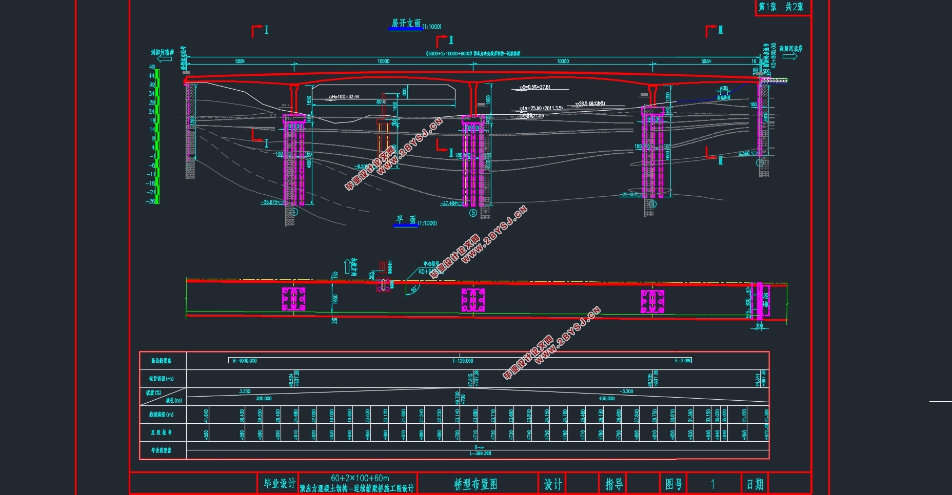
本次设计的目标是完成60+100×2+60m的浏阳河大桥的设计:设计基本内容包括完成桥梁设计总说明、上部结构、下部结构的计算及主要的施工图设计;拟选用刚构连续组合梁桥。该桥型主要优势:跨径较大,平顺舒适,造价上也有很强的竞争力等等。
桥梁总体布置及结构主要尺寸
设计依据及基本资料
设计标准
设计速度:60km/h。
设计荷载:公路—I级。
桥面净宽:净16m
桥面宽度:1.75m人行道+ 16m行车道+1.75m人行道=19.5m。
通航标准:内河Ⅴ级航道。
桥面横坡:车行道横坡采用2%,人行道横坡采用1.5%。
设计洪水频率:200年一遇。

目 录
摘要 I
Abstract II
第1章绪论 1
1.1桥梁方案选择 1
1.2刚构连续组合梁桥简介 1
1.3毕业设计目的及意义 1
第2章桥梁总体布置及结构主要尺寸 3
2.1设计依据及基本资料 3
2.1.1设计标准 3
2.1.2主要技术标准及采用规范 3
2.1.3主要材料 3
2.2桥跨布置 5
2.3上部结构尺寸拟定 5
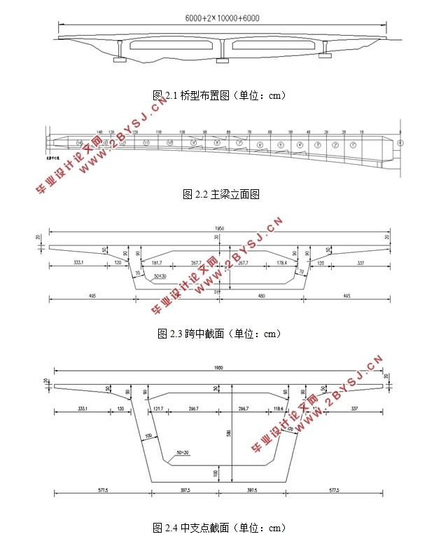
2.3.1顺桥向主梁尺寸拟定 5
2.3.2横桥向主梁尺寸拟定 6
2.4下部结构尺寸拟定 7
2.4.1墩身尺寸拟定 7
2.4.2桩基础尺寸拟定 7
2.4.3承台尺寸拟定 8
第3章建模 10
3.1模型简化 10
3.2主要参数说明 10
3.2.1材料参数 10
3.2.2荷载参数 11
3.2.3边界说明 12
3.3施工阶段说明 12
第4章桥梁结构内力计算 13
4.1恒载内力 13
4.2活载内力 16
第5章预应力钢筋设计 19
5.1纵向预应力筋估算 19
5.2预应力筋的布置 22
第6章截面几何特性 24
第7章预应力损失 26
7.1预应力钢筋与管道壁之间的摩擦 26
7.2锚具变形、钢筋回缩和接缝压缩 26
7.3预应力钢筋与台座之间的温差 27
7.4混凝土的弹性压缩 27
7.5预应力钢筋的应力松弛 27
7.6混凝土的收缩徐变 28
7.7预应力损失计算结果 28
第8章次内力计算及内力组合 32
8.1温度次内力 32
8.1.1计算依据及方法 32
8.1.2温度次内力计算结果 33
8.2基础不均匀沉降次内力 38
8.3预应力次内力 41
8.4收缩次内力 42
8.5徐变次内力 43
8.6内力组合 45
8.6.1承载能力极限状态组合 45
8.6.2正常使用极限状态组合 48
第9章主要截面验算 51
9.1承载能力极限状态截面验算 51
9.1.1正截面抗弯验算 51
9.1.2斜截面抗剪验算 55
9.2正常使用极限状态截面验算 56
9.2.1使用阶段正截面抗裂验算 56
9.2.2使用阶段斜截面抗裂验算 58
9.2.3挠度验算 61
9.3持久状况和短暂状况构件的应力验算 61
9.3.1使用阶段正截面压应力验算 61
9.3.2使用阶段斜截面主压应力验算 63
9.3.3施工阶段正截面法向应力验算 65
9.3.4受拉区钢筋的拉应力验算 68
第10章锚下局部承压验算 71
10.1局部受压区尺寸要求 71
10.2局部抗压承载力计算 72
第11章行车道板计算 73
11.1中间单向板计算 73
11.1.1恒载内力 73
11.1.2活载内力 73
11.1.3内力组合 77
11.2外边梁悬臂板内力计算 78
11.2.1恒载内力 78
11.2.2活载内力 78
11.2.3内力组合 79
11.3配筋设计 79
11.3.1支点处配筋 80
11.3.2跨中配筋 80
第12章桥墩内力计算 82
12.1内力计算 82
12.2配筋设计 82
第13章钻孔灌注桩计算 85
13.1桩径桩长拟定 85
13.2基桩根数及平面布置 85
13.3桩基础内力计算 86
13.4桩基础内力验算 88
13.5桩身配筋计算 88
参考文献 91
致谢 92