
电器盖注塑模具设计
无需注册登录,支付后按照提示操作即可获取该资料.
电器盖注塑模具设计(CAXA图纸8张,论文说明书5300字)
摘 要
本设计着重对模具结构的设计,因为注射模具结构是塑料模具设计的灵魂,它不仅决定了模具的功能,同时也决定了模具开发的成本和制造周期及操作的安全性。
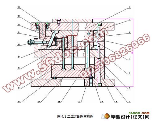
本模具型腔采用整体式结构,便于塑件的制造,有利于节约成本;型芯和型腔分别加工再配合一起,便于加工;定模板和定模座板采用螺钉固定。动模板和支承板,垫块,动模座板采用螺钉加销钉固定,保证了相对位置准确,提高了加工精度。推出机构采用推板推出,使推出阻力较小。推出机构用导柱与导套结合保证运动精度。采用侧浇口,本塑件采用一模两腔设计出的结构可确保模具工作运行可靠并能保证塑件的精度要求,提高材料利用率,与生产效率。
关键词:最优方案;熔体流动模拟;分型面;注射模
Abstract
The design focuses on the design of die structure, because the structure is plastic injection mold design and mold the soul, it not only determines the function of the mold, but also determines the cost of mold development and manufacturing cycle and operational security. The mold cavity using integrated structure, easy to manufacture plastic parts, is conducive to cost savings;, core and cavity, respectively, together with further processing, ease of processing; fixed templates and scheduled to die base plate with screws. Dynamic templates and support plate, pads, moving mold base plate with screw and pin fixed relative position to ensure accuracy, improve the processing accuracy. Introduced organizations launched by the push plate, so that launch resistance. Introduced organizations with guide post and guide sleeve combination to ensure movement accuracy. Using point gate, the plastic parts used to design a model structure of a cavity mold work to ensure reliable operation and to ensure the accuracy of plastic parts, improve material utilization, and production efficiency.
Key words: optimal solution; melt flow simulation; sub-surface; injection mold
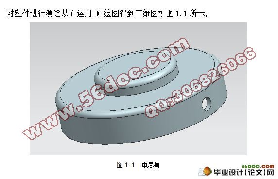
结构分析
从零件图上分析,该零件总体形状为圆形,总高度为17mm,外形直径尺寸为60mm,总体形状较为简单。壁厚为2mm,壁厚均匀。
目 录
摘 要 I
Abstract II
目 录 III
1 塑件造型及工艺分析 1
1.1 实体造型 1
1.2 塑件材料分析确定 1
1.2.1 材料分析 1
1.3 塑件的结构和尺寸精度表面质量分析 2
1.3.1 结构分析 2
1.3.2 精度分析 2
1.3.3 表面质量分析 2
2 注射方案和注射设备选择确定 4
2.1 确定模具结构方案 4
2.1.1 分型面的选择 4
2.1.2 型腔数目的确定 4
2.2 选择注射设备 4
2.2.1 计算注射量 4
2.2.2 选择注射设备 5
2.2.3 校核设备 5
3 成型部分结构设计 7
3.1成型零件的结构设计 7
3.1.1型腔的结构设计 7
3.1.2型芯的结构设计 7
3.2成型零件工作尺寸的计算 7
3.2.1型腔径向尺寸 8
3.2.2 型腔深度尺寸计算 8
3.2.3 型芯径向尺寸 8
3.2.4 型芯高度 8
3.2.5中心距尺寸 8
4 模具整体设计与标准件的选择 9
4.1 选择标准模架 9
4.2 建立浇注系统 9
4.2.1浇口套与定位圈的选择设计 9
4.2.2 浇口的设计 10
4.2.3 冷料穴的设计 10
4.3 脱模机构的设计 10
4.3.1 推出机构设计准则 10
4.3.2 推出力的确定 10
4.3.3 推出方式的确定 11
4.3.4 推板设计 11
4.4 冷却系统的设计计算 11
4.4.1 求塑件固化时每小时释放的热量Q 11
4.4.2 求冷却水的体积流量 12
4.4.3 冷却管道直径 12
4.4.4 求冷却水在管道内的流速v 12
4.4.5 求冷却管道孔壁与冷却水之间的传热膜系数 12
4.4.6 求冷却管道总传热面积 13
4.4.7 求模具上应开设的冷却管道的孔数n 13
4.5 完整模具展示 14
参考文献 15
致 谢 16